• Skip to primary navigation
  • Skip to main content

frankdenneman.nl

  • AI/ML
  • NUMA
  • About Me
  • Privacy Policy

vMotion and EtherChannel, an overview of the load-balancing policies stack

January 28, 2013 by frankdenneman

After posting the article “Choose link aggregation over Multi-NIC vMotion” I received a couple of similar questions. Pierre-Louis left a comment that covers most of the questions. Let me use this as an example and clarify how vMotion traffic flows through the stack of multiple load balancing algorithms and policies:

A question relating to Lee’s post. Is there any sense to you to use two uplinks bundled in an aggregate (LAG) with Multi-NIC vMotion to give on one hand more throughput to vMotion traffic and on the other hand dynamic protocol-driven mechanisms (either forced or LACP with stuff like Nexus1Kv or DVS 5.1)?
Most of the time, when I’m working on VMware environment, there is an EtherChannel (when vSphere < v5.1) with access datacenter switches that dynamically load balance traffic based on IP Hash. If i'm using LAG, the main point to me is that load balancing is done independently from the embedded mechanism of VMware (Active/Standby for instance).
Do you think that there is any issue on using LAG instead of using Active/Standby design with Multi-NIC vMotion? Do you feel that there is no interest on using LAG over Active/Standby (from VMware point of view and for hardware network point of view)?

Pierre-Louis takes a bottom-up approach when reviewing the stack of virtual and physical load-balancing policies and although he is correct when stating that network load balancing is done independently from VMware’s network stack, it does not have the impact he thinks it has. Lets look at the starting point of vMotion traffic and how that impacts both the flow of packets and utilization of links. Please read the articles “Choose link aggregation over Multi-NIC vMotion” and “Designing your vMotion network” to review some of the requirements of Multi-NIC vMotion configurations
Scenario configuration
Lets assume you have two uplinks in your host, i.e. two physical NICs per ESX host. Each vmnic used by the VMkernel NIC (vmknic) is configured as active and both links are aggregated in a Link Aggregation Group (LAG) (EtherChannel in Cisco terms).
01-network-configuration
First thing I want to clarify that the active/standby state of a vmknic is static and is controlled by the user, not a Load-Balancing policy. When using a LAG, both vmknics need to be configured active, as the load balancing policy needs to be able to send traffic across both links. Duncan explains the impact when using Standby NICs in an IP-Hash configuration.
Load balancing stack
A vMotion is initiated on host-level; therefor the first load balancer that comes in to play is vMotion itself. Then the portgroup load balancing policy will make a decision followed by the physical switch. Load balancing done by the physical switch/LAG is the last element in this stack.
Step 1: vMotion load balancing, this is done on the application layer and it is vMotion process that selects which VMkernel NIC is used. As you are using a LAG and two NICs, only one vMotion VMkernel NIC should exist. The previous mentioned article explains why you should designate all vmnics as active in a LAG. By using one vmknic enabled for vMotion, vMotion is unable to load-balance at vmknic level and sends all the traffic to the single vmknic.
Step 2: Next step is the load-balancing policy; IP-Hash will select one NIC after it hashes both source and destination IP. That means that this vMotion operation will use the same NIC until the vMotion operation is complete. It does not use two links, as a vMotion operation connection is setup by two VMkernel NICs and thus two IP-addresses (source IP address and destination IP). As IP-Hash determines the vmknic, traffic will be send out across the physical link.
Step 3: is at the physical switch layer and determines which port to use to connect to a NIC of the destination host. Once the physical switch receives the packet, the load balancer of the LAG configuration comes into play. The physical switch determines which path to take to the destination host according to utilization or availability of a link. Each switch vendor has different types of load balancers, too many to describe, the article “Understanding EtherChannel Load Balancing and Redundancy on Catalyst Switches” describes the different load balancing operations within the Cisco Catalyst switch family.
02-load-balancing-by-etherchannel
In short:
Step 1 Load balancing by vMotion: has no direct control over which physical NICs are used, it load balances across available multiple vmknics.
Step 2 Load balancing by IP-HASH: Outgoing connection is hashed based on its source and destination IP address; hash is used to select a physical NIC to use for network transmissions.
Step 3 Load balancing by LAG: Physical switch connected to destination performs the hash to choose which physical NIC to send incoming connection to.
To LAG or not to LAG, that’s the question
By using a LAG configuration for vMotion traffic, you are limited to the available bandwidth of a single uplink per vMotion operation as only one uplink is used per vMotion operation. A Multi-NIC vMotion configuration balances vMotion traffic across both VMkernel NICs. It load balances traffic for a single vMotion operation as well as multiple concurrent vMotion operations across the links. Let me state that differently; It is able to use the bandwidth of two uplinks for both a single vMotion operation, as well as multiple vMotion operations. With Multi-NIC vMotion you will get a more equal load balance distribution than with any load-balancing policy operating at NIC level.
I would always select multi-NIC vMotion over LAG. A LAG requires strict configuration on both virtual level as physical level. It’s a complex configuration on both technical and political level. Multiple departments need to be involved and throughout my years as an architect I seen many infrastructures fail due to inter-department politics. Troubleshooting a LAG configuration is not an easy task in an environment where there are communication-challenges between the server and the network department. Therefor I strongly prefer not to use LAG in a virtual infrastructure
Multiple single uplinks can be used to provide more bandwidth to the vMotion process and other load-balancing policies available on the distributed switch keep track of link utilization (LBT). It’s less complex, and in most cases give you better performance.

Filed Under: vMotion

Designing your vMotion networking – Choose link aggregation over Multi-NIC vMotion?

January 25, 2013 by frankdenneman

The “Designing your vMotion network” series have lead me to have some interesting conversations. A recurring question is why not use Link Aggregation technologies such as Etherchannel to increase bandwidth for vMotion operations. When zooming into vMotion load balancing operations and how the vNetwork load balancing operations work, it becomes clear that Multi-NIC vMotion network will provide a better performance that an aggregated link configuration.
Anatomy of vMotion configuration
In order to use vMotion a VMkernel network adapter needs to be configured. This network adapter needs to be enabled for vMotion and the appropriate load balancing policy and network adaptor failover mode needs to be selected.
00-multi-nic layers
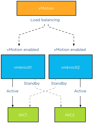
The vMotion load-balancing algorithm distribute vMotion traffic between the available VMkernel NICs, it does not consider the network configuration backing the VMkernel NIC (vmknic). vMotion expects that a vmknic is backed by a single active physical NIC, therefore when sending data to the vmknic the traffic will traverse a dedicated physical NIC. It’s important to understand that vMotion traffic flows between distinct vmknics! Migrating a virtual machine from a source host configured with Multi-NIC vMotion to a destination host with a single vmknic vMotion configuration result in the utilization of a single vmknic on the source host. Even though the single NIC vMotion is configured with two active uplinks, the source vMotion operation just selects one vmknic to transmit its data.
01-Multi-NIC-vMotion-to-Single-NIC-vMotion
Link aggregation
My esteemed colleague Vyenkatesh “ Venky” Deshpande published an excellent article on the new LACP functionality on the vSphere blog. Let me highlight a very interesting section:

Link aggregation allows you to combine two or more physical NICs together and provide higher bandwidth and redundancy between a host and a switch or between two switches. Whenever you want to create a bigger pipe to carry any traffic or you want to provide higher reliability you can make use of this feature. However, it is important to note that the increase in bandwidth by clubbing the physical NICs depends on type of workloads you are running and type of hashing algorithm used to distribute the traffic across the aggregated NICs.

And the last part is the key, when you aggregate links into a single logical link, it depends on the load balancing / hashing algorithm how the traffic is distributed across the aggregated links. When using an aggregated link configuration, it’s required to select the IP-HASH load balancing operation on the portgroup. I’ve published an article in 2011 called “IP-hash versus LBT” explaining how the hashing and distribution of traffic across a link aggregation group works.
Let’s assume you have Etherchannels in your environment and want to use it for your vMotion network. 2 x 1GB aggregated in one pipe, should beat 2 x 1GB right? As we learned vMotion deals only with vmknics and as vMotion detects a single vmknic it will send all the traffic to that vmknic.
02-vMotion-traffic-via-IP-HASH
The vMotion traffic hits the load-balancing policy configured on the portgroup and the IP-Hash algorithm will select a vmnic to transmit the traffic to the destination host. Yes you read it correct, although the two links are aggregated the IP-Hash load balancing policy will always select a single NIC to send traffic. Therefor vMotion will use a single uplink (1GB in this example) to transfer vMotion traffic. With IP-hash a vMotion operation utilizes a single link, leaving the other NIC idle. Would you have used Multi-NIC vMotion, vMotion would have balanced the traffic across the multiple vmknics even for a single vMotion operation.
Utilization aware
Using the same scenario, vMotion determines that this host is allowed to have 4 concurrent vMotion operations. Unfortunately IP-Hash does not take utilization into account when selecting the NIC. The selection is done on a source-destination IP hash, decreasing the probability of load balancing across multiple NICs when using a small number of IP-addresses. This situation is often applicable to the vMotion subnet; this subnet contains a small number of IP-addresses used by the vMotion vmknics. Possibly resulting IP-HASH selecting the same NIC for the same concurrent vMotion operations. This in turn may lead to oversaturating a single uplink while leaving the other uplink idling. Would you have used Multi-NIC vMotion, vMotion would have balanced the traffic across the multiple vmknics, providing an overall utilization of both NICs.
Key takeaways
Link aggregation does not provide a big fat pipe to vMotion, due to the IP-Hash load balancing policy, a single nic will be used for a vMotion operation. IP-Hash is not utilization aware, possibly distributing traffic unevenly due to small number of source and destination IP-addresses. Multi-NIC vMotion distributes vMotion traffic across all available vmknics, for both single vMotion operations and multiple concurrent vMotion operations. Multi-NIC vMotion provides a better overall utilization of NICs allocated for the vMotion processes.
Part 1 – Designing your vMotion network
Part 2 – Multi-NIC vMotion failover order configuration
Part 3 – Multi-NIC vMotion and NetIOC
Part 5 – 3 reasons why I use a distributed switch for vMotion networks
Filed Under: vMotion

New technical paper: The CPU Scheduler in VMware vSphere 5.1

January 24, 2013 by frankdenneman

Today a new technical paper is available on vmware.com.
Description
The CPU scheduler is an essential component of vSphere 5.x. All workloads running in a virtual machine must be scheduled for execution and the CPU scheduler handles this task with policies that maintain fairness, throughput, responsiveness, and scalability of CPU resources. This paper describes these policies, and this knowledge may be applied to performance troubleshooting or system tuning. This paper also includes the results of experiments on vSphere 5.1 that show the CPU scheduler maintains or exceeds its performance over previous versions of vSphere.
If you are interested in CPU scheduling and in particular NUMA, download the paper: The CPU Scheduler in VMware vSphere 5.1

Filed Under: VMware

Hide all Getting Started Pages in vSphere 5.1 webclient in 3 easy steps

January 23, 2013 by frankdenneman

I’m rebuilding my lab and after I installed a new vCenter server I was confronted with those Getting Started tabs again. That reminded me that I promised someone at a VMUG to blog how to remove these tabs in one single operation.

  1. Go to Help (located in the blue bar top right of your screen)
  2. Click on the arrow
  3. Select Hide All Getting Started Pages

Hide-All-Getting-Started-Pages

Filed Under: VMware

Direct IP-storage and using NetIOC User-defined network resource pools for QoS

January 21, 2013 by frankdenneman

Some customers use iSCSI initiators inside the Guest OS to connect directly to a datastore on the array or using an NFS client inside the Guest OS to access remote NFS storage directly. Thereby circumventing the VMkernel storage stack of the ESX host. The virtual machine connects to the remote storage system via a VM network portgroup and therefore the VMkernel classifies this network traffic as virtual machine traffic. This “indifference” or non-discriminating behavior of the VMkernel might not suit you or might not help you to maintain service level agreements.
Isolate traffic
In the 1Gbe adapter world, having redundant and isolated uplinks assigned for different sorts of traffic is a simple way of not to worry about traffic congestion. However when using a small number of 10GbE adapters you need to be able to partition network bandwidth among the different types of network traffic flows. This is where NetIOC comes into play. Please read the “Primer on Network I/O Control” article to quickly brush up on your knowledge of NetIOC.
System network resource pools
By default NetIOC provides seven different system network resource pools. Six network pools are used to bind VMkernel traffic, such as NFS and iSCSI. One system network resource pool is used for virtual machine network traffic.
03-system network resource pools
The network adapters you use to connect your IP-Storage from within the Guest OS connect to a virtual machine network portgroup. Therefor NetIOC binds this traffic to the virtual machine network resource pool. In result this traffic shares the bandwidth and prioritization with “common” virtual machine network traffic.
01-vm-portgroup-mapping-to-virtual-machine-portgroup
User-defined network resource pool
Most customers tend to prioritize IP storage traffic over network traffic induced by applications and the guest-OS. To ensure the IP-Storage traffic created by the NFS client or iSCSI initiator inside the Guest OS create a user-defined network resource pool. User-defined network resource pools are available from vSphere 5.0 and upwards. Make sure your distributed switch is at least version 5.0.
Shares: User-defined network resource pools are available to isolate and prioritize virtual machine network traffic. Configure the User-defined network resource pool with an appropriate number of shares. The number of shares will reflect the relative priority of this network pool compared to the other traffic streams using the same dvUplink.
QoS tag: Another benefit of creating a separate User-defined network resource pool is the ability to set a QoS tag specifically for this traffic stream. If you are using IEEE 802.1p tagging end-to-end throughout your virtual infrastructure ecosystem, setting the QoS tag on the User-defined network resource pool helps you to maintain the service level for your storage traffic.
011-user-defined-network-resource-pool
Setup
In a greenfield scenario setup the User-defined resource pool first, that allows you to select the correct network pool during the creation of the dvPortgroups. If you already created dvPortgroups, you can assign the correct network resource pool once you create the network resource pool.
Create a user defined network resource pool:
1. Open your vSphere web client and go to networking.
2. Select the dvSwitch
3. Go to Manage
4. Select Resource Allocation tab
5. Click on the new icon.
6. Configure the network resource pool and click on OK
04-New-Network-Resource-Pool
I already made a User-defined network resource pool called dNFS, the overview of available network resource pools on the dvSwitch looks like this:
02-network-pools-overview
To map the network resource pool to the Distributed Port Group, create a new Distributed Port group, or edit an existing one and select the appropriate network resource pool:
03-new-distributed-portgroup

Filed Under: Networking

  • « Go to Previous Page
  • Page 1
  • Interim pages omitted …
  • Page 48
  • Page 49
  • Page 50
  • Page 51
  • Page 52
  • Interim pages omitted …
  • Page 89
  • Go to Next Page »

Copyright © 2025 · SquareOne Theme on Genesis Framework · WordPress · Log in