By default a virtual machine swap file is stored in the working directory of the virtual machine. However, it is possible to configure the hosts in the DRS cluster to place the virtual machine swapfiles on an alternative datastore. A customer asked if he could create a datastore cluster exclusively used for swap files. Although you can use the datastores inside the datastore cluster to store the swap files, Storage DRS does not load balance the swap files inside the datastore cluster in this scenario. Here’s why:
Alternative swap location
This alternative datastore can either be a local datastore or a shared datastore. Please note that placing the swapfile on a non-shared local datastore impacts the vMotion lead-time, as the vMotion process needs to copy the contents of the swap file to the swapfile location of the destination host. However a datastore that is shared by the host inside the DRS cluster can be used, a valid use case is a small pool of SSD drives, providing a platform that reduces the impact of swapping in case of memory contention.
Storage DRS
What about Storage DRS and using alternative swap file locations? By default a swap file is placed in the working directory of a virtual machine. This working directory is “encapsulated” in a DRMdisk. A DRMdisk is the smallest entity Storage DRS can migrate. For example when placing a VM with 3 hard disks in a datastore cluster, Storage DRS creates 4 DRMdisks, one DRMdisk for the working directory and separate DRMdisks for each hard disk.
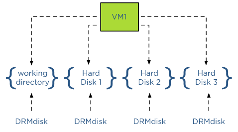
Extracting the swap file out of the working directory DRMdisk
When selecting an alternative location for swap files, vCenter will not place this swap file in the working directory of the virtual machine, in essence extracting it from – or placing it outside – the working directory DRMdisk entity. Therefore Storage DRS will not move the swap file during load balancing operations or maintenance mode operations as it can only move DRMdisks.
Alternative Swap file location a datastore inside a datastore cluster?
Storage DRS does not encapsulate a swap file in its own DRMdisk and therefore it is not recommended to use a datastore that is part of a datastore cluster as a DRS cluster swap file location. As Storage DRS cannot move these files, it can impact load-balancing operations.
The user interface actually reveals the incompatibility of a datastore cluster as a swapfile location because when you configure the alternate swap file location, the user interface only displays datastores and not a datastore cluster entity.
DRS responsibility
Storage DRS can operate with swap files placed on datastores external to the datastore cluster. It will move the DRMdisks of the virtual machines and leave the swap file on its specified location. It is the task of DRS moving the swap file if it’s placed on a non-shared swap file datastore when migrating the compute state between two hosts.
Get notification of these blogs postings and more DRS and Storage DRS information by following me on Twitter: @frankdenneman
Partially connected datastore clusters – where can I find the warnings and how to solve it via the web client?
During my Storage DRS presentation at VMworld I talked about datastore cluster architecture and covered the impact of partially connected datastore clusters. In short – when a datastore in a datastore cluster is not connected to all hosts of the connected DRS cluster, the datastore cluster is considered partially connected. This situation can occur when not all hosts are configured identically, or when new ESXi hosts are added to the DRS cluster.
The problem
I/O load balancing does not support partially connected datastores in a datastore cluster and Storage DRS disables the IO load balancing for the entire datastore cluster. Not only on that single partially connected datastore, but the entire cluster. Effectively degrading a complete feature set of your virtual infrastructure. Therefore having an homogenous configuration throughout the cluster is imperative.
Warning messages
An entry is listed in the Storage DRS Faults window. In the web vSphere client:
1. Go to Storage
2. Select the datastore cluster
3. Select Monitor
4. Storage DRS
5. Faults.

The connectivity menu option shows the Datastore Connection Status, in the case of a partially connected datastore, the message Datastore Connection Missing is listed.

When clicking on the entry, the details are shown in the lower part of the view:

Returning to a fully connected state
To solve the problem, you must connect or mount the datastores to the newly added hosts. In the web client this is considered a host-operation, therefore select the datacenter view and select the hosts menu option.
1. Right-click on a newly added host
2. Select New Datastore
3. Provide the name of the existing datastore

4. Click on Yes when the warning “Duplicate NFS Datastore Name” is displayed.

5. As the UI is using existing information, select next until Finish.
6. Repeat steps for other new hosts.
After connecting all the new hosts to the datastore, check the connectivity view in the monitor menu of the of the datastore cluster

Get notification of these blogs postings and more DRS and Storage DRS information by following me on Twitter: @frankdenneman
Storage DRS automation level and initial placement behavior
Recently I was asked why Storage DRS was missing a “Partially Automated mode”. Storage DRS has two automation levels, no automation (Manual Mode) and Fully Automated mode. When comparing this with DRS, we notice that Storage DRS is missing a “Partially Automated mode”. But in reality the modes of Storage DRS cannot be compared to DRS at all. This article explains the difference in behavior.
DRS automation modes:
There are three cluster automation levels:
Manual automation level:
When a virtual machine is configured with the manual automation level, DRS generate both initial placement and load balancing migration recommendations, however the user needs to manual approve these recommendations.
Partially automation level:
DRS automatically places a virtual machine with a partially automation level, however it will generate a migration recommendation which requires manual approval.
Fully automated level:
DRS automatically places a virtual machine on a host and vCenter automatically applies migration recommendation generated by DRS
Storage DRS automation modes:
There are two datastore cluster automation levels:
No Automation (Manual mode):
Storage DRS will make migration recommendations for virtual machine storage, but will not perform automatic migrations.
Fully Automated:
Storage DRS will make migration recommendations for virtual machine storage, vCenter automatically confirms migration recommendations.
No automatic Initial placement in Storage DRS
Storage DRS does not provide placement recommendations for vCenter to automatically apply. (Remember that DRS and Storage DRS only generate recommendations, it is vCenter that actually approves these recommendations if set to Automatic). The automation level only applies to migration recommendation of exisiting virtual machines inside the datastore cluster. However, Storage DRS does analyze the current state of the datastore cluster and generates initial placement recommendations based on space utilization and I/O load of the datastore and disk footprint and affinity rule set of the virtual machine.
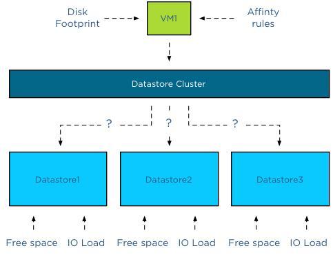
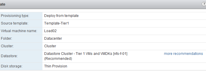
When provisioning a virtual machine, the summary screen provided in the user interface displays a datastore recommendation.
When clicking on the “more recommendations” less optimal recommendations are displayed.
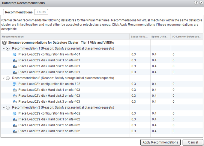
This screen provides information about the Space Utilization % before placement, the Space Utilization % after the virtual machine is placed and the measured I/O Latency before placement. Please note that even when I/O load balancing is disabled, Storage DRS uses overall vCenter I/O statistics to determine the best placement for the virtual machine. In this case the I/O Latency metric is a secondary metric, which means that Storage DRS applies weighing to the space utilization and overall I/O latency. It will satisfy space utilization first before selecting a datastore with an overall lower I/O latency.

Adding new hard-disks to a existing VM in a datastore cluster
As vCenter does not apply initial placement recommendations automatically, adding new disks to an existing virtual machine will also generate an initial placement recommendation. The placement of the disk is determined by the default affinity cluster rule. The datastore recommendation depicted below shows that the new hard disk is placed on datastore nfs-f-01, why? Because it needs to satisfy storage initial placement requests and in this case this means satisfying the datastore cluster default affinity rule.
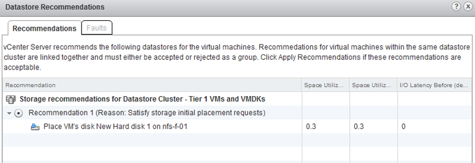
If the datastore cluster were configured with a VMDK anti-affinity rule, the datastore recommendation would show any other datastore except datastore nfs-f-01.
Get notification of these blogs postings and more DRS and Storage DRS information by following me on Twitter: @frankdenneman
Storage DRS Device Modeling behavior
During a recent meeting the behavior of Storage DRS device modeling was discussed. When I/O load balancing is enabled, Storage DRS leverages the SIOC injector to determine the device characteristics of the disks backing the datastore. Because the injector stops when there is activity detected on the datastore, the customer was afraid that Storage DRS wasn’t able to get a proper model of his array due to the high levels of activity seen on the array. Storage DRS was designed to cope with these environments, as the customer was reassured after explaining the behavior I thought it might be interesting enough for to share it with you too.
The purpose of device modeling
Device modeling is used by Storage DRS to characterize the performance levels of the datastore. This information is used when Storage DRS needs to predict the benefit of a possible migration of a virtual machine. The workload model provides information about the I/O behavior of the VM, Storage DRS uses that as input and mixes this with the device model of the datastore in order to predict the increase of latency after the move. The device modeling of the datastore is done with the SIOC injector
The workload
To get a proper model, the SIOC injector injects random read I/O to the disk. SIOC uses different amounts of outstanding IO to measure the latency. The duration of the complete cycle is 30 seconds and is trigger once a day per datastore. Although it’s a short-lived process, this workload does generate some overhead on the array and Storage DRS is designed to enable storage performance for your virtual machines, not to interfere with them. Therefor this workload will not run when activity is detected on the devices backing the datastore.
Timer
As mentioned, the device modeling process runs for 30 seconds in order to characterize the device. If the IO injector starts and the datastore is active or becomes active, the IO injector will wait for 1 minute to start again. If the datastore is still busy, it will try again in 2 minutes, after that it idles for 4 minutes, after that 8 minutes, 16 minutes, 32 minutes, 1 hour and finally 2 hours. When the datastore is still busy after two hours after the initial start it will try to start the device modeling with an interval of 2 hours until the end of the day.
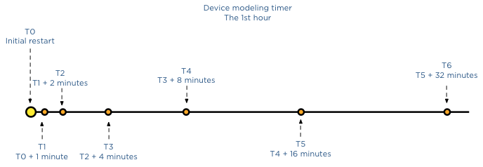
If SIOC is not able to characterize the disk during that day, it will use the average value of all the other datastores in other not to influence the load balancing operations with false information and provide information that would favor this disk over other datastores that did provide actual data.
The next day SIOC injector will try model the device again, but uses a skew back and forth of 2 hours from the previous period, this way during the year, Storage DRS will retrieve info across every period of the day.
Key takeway
Overall we do not expect the array to be busy 24/7, there is always a window of 30 seconds where the datastore is idling. Having troubleshooting many storage related problems I know arrays are not stressed all day long, therefor I’m more than confident that Storage DRS will have accurate device models to use for its prediction models.
Get notification of these blogs postings and more DRS and Storage DRS information by following me on Twitter: @frankdenneman
Avoiding VMDK level over-commitment while using Thin disks and Storage DRS
The behavior of thin provisioned disk VMDKs in a datastore cluster is quite interesting. Storage DRS supports the use of thin provisioned disks and is aware of both the configured size and the actual data usage of the virtual disk. When determining placement of a virtual machine, Storage DRS verifies the disk usage of the files stored on the datastore. To avoid getting caught out by instant data growth of the existing thin disk VMDKs, Storage DRS adds a buffer space to each thin disk. This buffer zone is determined by the advanced setting “PercentIdleMBinSpaceDemand”. This setting controls how conservative Storage DRS is with determining the available space on the datastore for load balancing and initial placement operations of virtual machines.
IdleMB
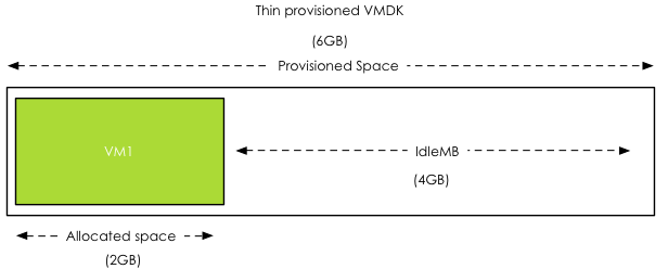
The main element of the advanced option “PercentIdleMBinSpaceDemand” is the amount of IdleMB a thin-provisioned VMDK disk file contains. When a thin disk is configured, the user determines the maximum size of the disk. This configured size is referred to as “Provisioned Space”. When a thin disk is in use, it contains an x amount of data. The size of the actual data inside the thin disk is referred to as “allocated space”. The space between the allocated space and the provisioned space is called identified as the IdleMB. Let’s use this in an example. VM1 has a single VMDK on Datastore1. The total configured size of the VMDK is 6GB. VM1 written 2GB to the VMDK, this means the amount of IdleMB is 4GB.
PercentIdleMBinSpaceDemand
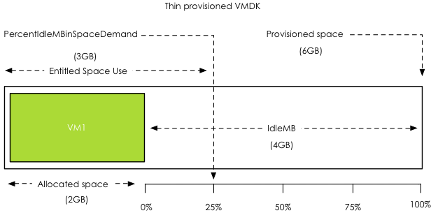
The PercentIdleMBinSpaceDemand setting defines percentage of IdleMB that is added to the allocated space of a VMDK during free space calculation of the datastore. The default value is set to 25%. When using the previous example, the PercentIdleMBinSpaceDemand is applied to the 4GB unallocated space, 25% of 4GB = 1 GB.
Entitled Space Use
Storage DRS will add the result of the PercentIdleMBinSpaceDemand calculation to the consumed space to determine the “entitled space use”. In this example the entitled space use is: 2GB + 1GB = 3GB of entitled space use.
Calculation during placement
The size of Datastore1 is 10GB. VM1 entitled space use is 3GB, this means that Storage DRS determines that Datastore1 has 7GB of available free space.
Changing the PercentIdleMBinSpaceDemand default setting
Any value from 0% to 100% is valid. This setting is applied on datastore cluster level. There can be multiple reasons to change the default percentage. By using 0%, Storage DRS will only use the allocated space, allowing high consolidation. This is might be useful in environments with static or extremely slow data increase.
There are multiple use cases for setting the percentage to 100%, effectively disabling over-commitment on VMDK level. Setting the value to 100% forces Storage DRS to use the full size of the VMDK in its space usage calculations. Many customers are comfortable managing over-commitment of capacity only at storage array layer. This change allows the customer to use thin disks on thin provisioned datastores.
Use case 1: NFS datastores
A use case is for example using NFS datastores. Default behavior of vSphere is to create thin disks when the virtual machine is placed on a NFS datastore. This forces the customer to accept a risk of over-commitment on VMDK level. By setting it to 100%, Storage DRS will use the provisioned space during free space calculations instead of the allocated space.
Use case 2: Safeguard to protect against unintentional use of thin disks
This setting can also be used as safeguard for unintentional use of thin disks. Many customers have multiple teams for managing the virtual infrastructure, one team for managing the architecture, while another team is responsible for provisioning the virtual machines. The architecture team does not want over-commitment on VMDK level, but is dependent on the provisioning team to follow guidelines and only use thick disks. By setting “PercentIdleMBinSpaceDemand” to 100%, the architecture team is ensured that Storage DRS calculates datastore free space based on provisioned space, simulating “only-thick disks” behavior.
Use-case 3: Reducing Storage vMotion overhead while avoiding over-commitment
By setting the percentage to 100%, no over-commitment will be allowed on the datastore, however the efficiency advantage of using thin disks remains. Storage DRS uses the allocated space to calculate the risk and the cost of a migration recommendation when a datastore avoids its I/O or space utilization threshold. This allows Storage DRS to select the VMDK that generates the lowest amount of overhead. vSphere only needs to move the used data blocks instead of all the zeroed out blocks, reducing CPU cycles. Overhead on the storage network is reduced, as only used blocks need to traverse the storage network.
Get notification of these blogs postings and more DRS and Storage DRS information by following me on Twitter: @frankdenneman