• Skip to primary navigation
  • Skip to main content

frankdenneman.nl

  • AI/ML
  • NUMA
  • About Me
  • Privacy Policy

Gen AI Sessions at Explore Barcelona 2023

November 1, 2023 by frankdenneman

I’m looking forward to next week’s VMware Explore conference in Barcelona. It’s going to be a busy week. Hopefully, I will meet many old friends, make new friends, and talk about Gen AI all week. I’m presenting a few sessions, listed below, and meeting with customers to talk about the VMware Private AI foundation. If you are interested and you see me, walk by, come, and have a talk with me.

Hopefully, I will see you at one of the following sessions:

Monday, Nov 6:
Executive Summit
For invite only
Time: 11:00 AM – 1:00 PM CET

For VMware Certified Instructors only: VCI Forum Keynote.
Time: 2:15 PM – 3:00 PM CET
Location: Las Arenas II (2) Hotel Porta Fira, Pl. d’Europa, 45, 08908 L’Hospitalet de Llobregat, Barcelona, Spain 15 min walk from conference, 3 min taxi)

Meet the Experts Sessions
Machine Learning Accelerator Deep Dive [CEIM1199BCN]
Time: 4:30 PM – 5:00 PM CET
Location: Hall 8.0, Meet the Experts, Table 4

Tuesday, Nov 7:
Meet the Experts Sessions
Machine Learning Accelerator Deep Dive [CEIM1199BCN]
Time: 11:30 AM – 12:00 PM CET
Location: Hall 8.0, Meet the Experts, Table 1

Wednesday, Nov 8:
AI and ML Accelerator Deep Dive [CEIB1197BCN]
Time: 9:00 AM – 9:45 AM CET
Location: Hall 8.0, Room 31

CTEX: Building a LLM Deployment Architecture: Five Lessons Learned
Speakers: Shawn Kelly & Frank Denneman
Time: 4:00 PM – 5:00 PM CET
Location: Room CC5 501
Register here: https://lnkd.in/eiTbZusU

Recommended AI Sessions:
Monday, Nov 6:
‘Til the Last Drop of GPU: Run Large Language Models Efficiently [VIT2101BCN] (Tutorial)
Speakers: Agustin Malanco – Triple VCDX
Time: 11:00 AM – 12:30 PM CET
Location: Hall 8.0, Room 18

Tuesday, Nov 7:
Using VMware Private AI for Large Language Models and Generative AI on VMware Cloud Foundation and VMware vSphere [CEIB2050BCN]
Speakers: Justin Murray, Shawn Kelly
Time: 10:30 AM – 11:15 AM CET 
Location: Hall 8.0, Room 12

Empowering Business Growth with Generative AI [VIB2368BCN]
Speakers: Robbie Jerrom, Serge Palaric, Shobhit Bhutani
Time: 2:15 PM – 3:00 PM CET 
Location: Hall 8.0, Room 14

Why do I need AI in my Data Center? Does this help me become a differentiator?
Speaker: Gareth Edwards.
Time: Nov 7, 3:30 – 4:40 PM 
Location: CTEX: Room CC5 501

Meet the Experts:
ML/AI and Large Language Models – Implications for VMware Infrastructure [CEIM2282BCN]
Expert: Justin Murray
Time: 12:30 PM – 1:00 PM CET
Location: Hall 8.0, Meet the Experts, Table 2

Wednesday, Nov 8
AI Without GPUs: Run AI/ML Workloads on Intel AMX CPUs with vSphere 8 and Tanzu [MAPB2367BCN]
Speakers: Chris J Gully, Earl Ruby
Time: 12:45 PM – 1:30 PM CET
Location: Hall 8.0, Room 33

Meet the Experts:
ML/AI and Large Language Models – Implications for VMware Infrastructure [CEIM2282BCN]
Expert: Justin Murray
Time: 4:30 PM – 5:00 PM CET
Location: Hall 8.0, Meet the Experts, Table 4
Filed Under: Uncategorized

Sapphire Rapids Memory Configuration

February 28, 2023 by frankdenneman

The 4th generation of the Intel Xeon Scalable Processors (codenamed Sapphire Rapids) was released early this year, and I’ve been trying to wrap my head around what’s new, what’s good, and what’s challenging. Besides those new hardware native accelerators, which a later blog post covers, I noticed the return of different memory speeds when using multiple DIMMs per channel.

Before the Scalable Processor Architecture in 2017, you faced the devil’s triangle when configuring memory capacity, cheap, high capacity, fast, pick two. The Xeons offered four memory channels per CPU package, and each memory channel could support up to three DIMMs. The memory speed decreased when equipped with three DIMMs per channel (3 DPC).

Skylake, the first Scalable Processor generation, introduced six channels; each supporting a maximum of two DIMMs, with no performance degradation between 1 DPC or 2 DPC configurations. However, most server vendors introduced a new challenge by only selling servers with 8 DIMM slots instead of 12, and thus unbalanced memory configurations were introduced when all DIMM slots were populated. Unbalanced memory configuration negatively impacts performance. Dell and others have reported drops in memory bandwidth between 35% to 65%.

The 3rd generation of the Scalable Processor Architecture introduced eight channels of DDR4 per CPU. To solve the server vendors’ unbalanced memory configuration problem and provide parity to the AMD EPYC memory configuration. It also meant we were back to the “natural” order of base 10 memory capacity configuration, 256, 512, 1024,2048. Many servers weren’t following the optimal 6-channel configuration of 384, 768, and 1536; for some admins, it felt unnatural.

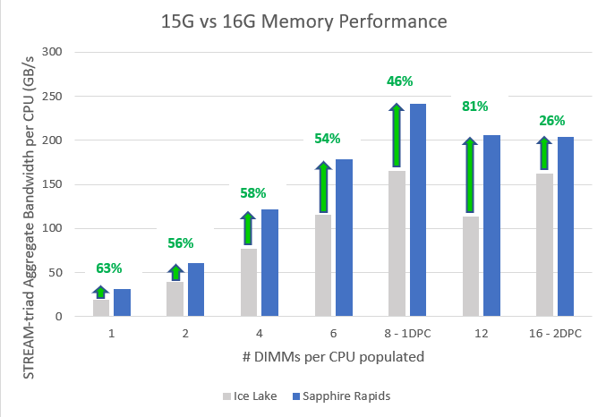
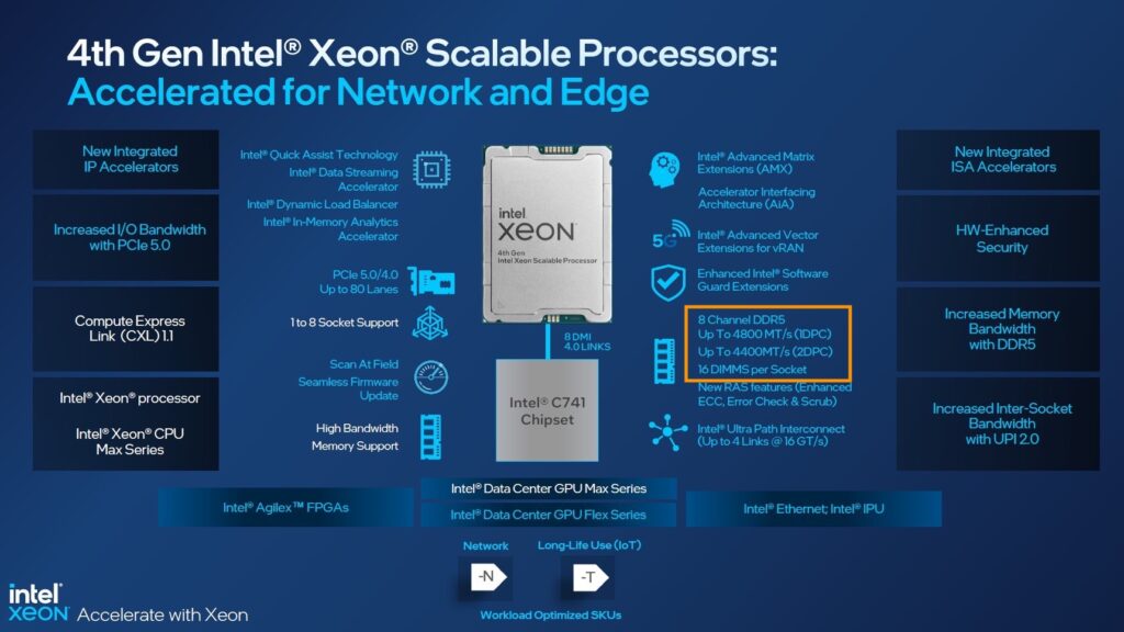
And this brings me to the 4th generation, the Sapphire Rapids. It provides eight channels of DDR5 per CPU with a maximum memory speed of 4800 MHz. Compared to the 3rd generation, it results in up to 50% more aggregated bandwidth as the Ice Lake generation supports eight channels using DDR4 3200 MHz. But the behavior between the 3rd and the 4th generation differ when pushing them to their max capacity.

With Sapphire Rapids, each CPU has eight memory controllers, providing high-speed throughput and allowing advanced sub-NUMA clustering configurations similar to the AMD EPYC of four clusters within a single CPU (An upcoming blog post covers this topic in-depth). These features sound very promising. However, Intel reintroduced different memory speeds when loading the memory channel with multiple DIMMs.

Sapphire Roads supports multiple memory speeds. The bronze and silver families support a maximum memory speed of 4000 MHz. The Gold family is all over the place, supporting a maximum of 4000, 4400, and 4800 MHz. The Platinum family supports up to 4800 MHz. However, this is in a 1 DPC configuration. 4400 MHz in a 2 DPC configuration.

The massive step up from 3200 MHz to 4800 MHz is slightly reduced when loading the server with more than eight DIMMs per CPU. When comparing theoretical bandwidth speeds, 1 DPC and 2 DPC, bandwidth performance looks as follows:

DDR4 3200 MHZ provides a theoretical bandwidth of 25.6 GB/s. DDR5 4800 MHz provides a theoretical bandwidth of 38.2 GB/s, while 4400 MHz DDR5 memory provides a theoretical bandwidth of 35.2 GB/s.

Xeon Architecture1 DPCGB/s8 Ch+%2 DPCGB/s16 Ch+%
3rd Gen Xeon3200 MHz23.4204.8 GB/s3200 MHz25.6409.6 GB/s
4th Gen Xeon4800 MHz38.4307.2 GB/s50%4400 MHz35.2563.2 GB/s37.5%

Dell published a report of performance study measuring memory bandwidth using the STREAM Triad benchmark. The study compared the performance of the 3rd and 4th generation Xeons and shows “real” bandwidth numbers. Sapphire Rapids improves memory bandwidth by 46% in a 1 DPC configuration, “but only” 26% in a 2 DPC configuration. Although STREAM is a synthetic benchmark, it does give us a better idea of what bandwidth to expect in real life.

I hope this information helps to guide you when configuring the memory configuration of your next vSphere ESXi host platform. Selecting the right DIMM capacity can quickly get 20% better memory performance.

Filed Under: CPU, Uncategorized

vSphere 8 CPU Topology for Large Memory Footprint VMs Exceeding NUMA Boundaries

November 3, 2022 by frankdenneman

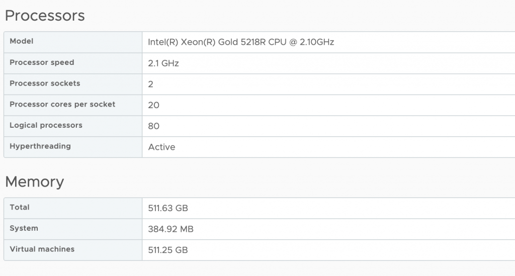
By default, vSphere manages the vCPU configuration and vNUMA topology automatically. vSphere attempts to keep the VM within a NUMA node until the vCPU count of that VM exceeds the number of physical cores inside a single CPU socket of that particular host. For example, my lab has dual-socket ESXi host configurations, and each host has 20 processor cores per socket. As a result, vSphere creates a VM with a vCPU topology with a unified memory address (UMA) up to the vCPU count of 20. Once I assign 21 vCPU, it creates a vNUMA topology with two virtual NUMA nodes and exposes this to the guest OS for further memory optimization.

You might have noticed that vNUMA topology sizing is structured around vCPU and physical core count. But what happens when the virtual machine configuration fits inside the NUMA node with its vCPU configuration, i.e., has less vCPU than the CPU has physical cores? But the VM requires more memory than the NUMA node can provide. I.e., the VM configuration exceeds the local memory configuration of the NUMA node.

As a test, I’ve created a VM with 12 vCPUs and 384GB. The vCPU configuration fits a single NUMA node (12<20), but the memory configuration of 384GB exceeds the 256GB of each NUMA node.

By default, vSphere creates the vCPU topology and exposes a unified memory address to the guest OS. For scheduling purposes, it creates two separate scheduling constructs to allocate the physical memory from both NUMA nodes but just doesn’t exposes that information to the guest OS. Inconsistent performance results from this situation, as the guest OS just starts to allocate the memory from the beginning of the memory range to the end without knowing anything about the physical origins. As a test, an application is running that allocates 380GB. As all the vCPU run in a single NUMA node, the memory scheduler will do its best and allocate the memory as close to the vCPUs as possible. As a result, the memory scheduler can allocate 226 GB locally (237081912 KB by vm.8823431) while having to allocate the rest from the remote NUMA node (155 GB).

Latency on an Intel for local NUMA nodes hovers around 73ns for a Xeon v4 and 89ns for a Skylake generation. At the same time, remote memory is about 130ns for a v4 and 139ns for a Skylake, AMD Epyc local is 129ns, and remote memory is 205ns. On Intel, that is a performance impact of 73% v4 and 56% on Skylake. On AMD, having to fetch remote memory will slow it down by 56%. That means, in this case, the application fetches 31% of its memory with a 73% latency penalty.

Another problem with this setup is that this VM is now quite an unbalanced noisy neighbor. There is little to do about monster VMs in your system, but this VM has an unbalanced memory footprint. It eats up most of the memory of NUMA node 0. I would rather see a more balanced footprint to utilize other cores on the NUMA node and enjoy local memory access. In this scenario, new virtual machines are forced to retrieve their memory from the other NUMA node if they are scheduled alongside this VM from a vCPU perspective.

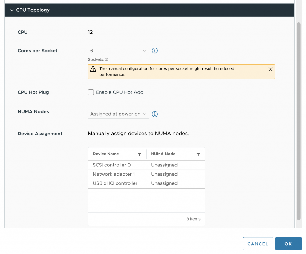
To solve this problem, we used to set the advanced setting “numa.consolidate = FALSE” in vSphere 7 and older versions. vSphere 8 provides the option to configure the vCPU topology and, specifically, the vNUMA topology from the UI that solves the aforementioned problem. In the VM options of the VM configuration vSphere 8 includes the option CPU Topology.

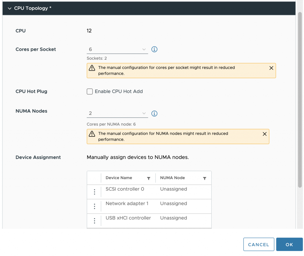
By default, the Cores per Socket and NUMA Nodes settings are “assigned at power on,” which is the recommended setting for most workloads. In our case, we want to change it, and first, we have to change the Cores per Socket settings before we can adjust the NUMA Nodes setting. It’s best to distribute the vCPUs equally across the physical NUMA nodes so that each group of vCPU can allocate an equal amount of memory capacity. The VM configuration is set to 6 cores per socket in our test case, creating two vSockets.

The next step is to configure the virtual NUMA nodes. Aligning this with the underlying physical configuration helps to get the best predictable and consistent performance behavior for the virtual machine. In our case, the VM is configured with two NUMA nodes.

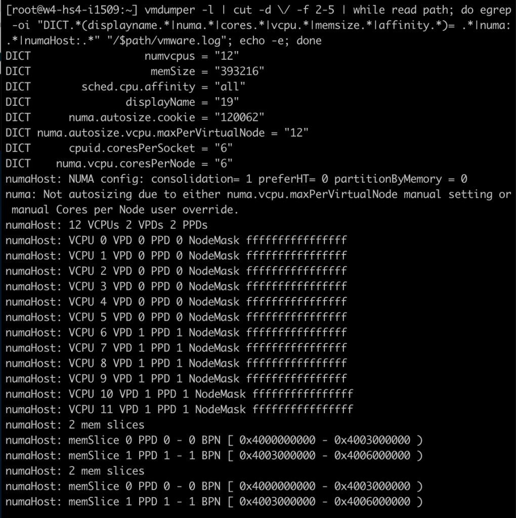
After the virtual machine is powered-on, I opened up a SSH session to the ESXi host and ran the following command: “vmdumper -l | cut -d \/ -f 2-5 | while read path; do egrep -oi “DICT.(displayname.|numa.|cores.|vcpu.|memsize.|affinity.)= .|numa:.|numaHost:.” “/$path/vmware.log”; echo -e; done”

That provided me with the following output; notice the following lines:
cpuid.coresPerSocket = “6”
numa.vcpu.coresPerNode = “6”
numaHost 12 VCPUs 2 VPDs 2 PPDs

It shows that the VM is configured with 12 vCPUs, 6 cores per socket, 6 vCPUs per NUMA node. At the ESXi scheduling level, the NUMA scheduler creates two scheduling constructs. A virtual proximity domain (VPD) is a construct used to expose a CPU topology to the guest OS. You can see that it has created two VPDs for this VM. VPD 0 contains VCPU 0 to VCPU 5, and VPD 1 contains VCPU 6 to VCPU 11. A PPD is a physical proximity domain and is used by the NUMA scheduler to assign a PPD to a physical NUMA node.

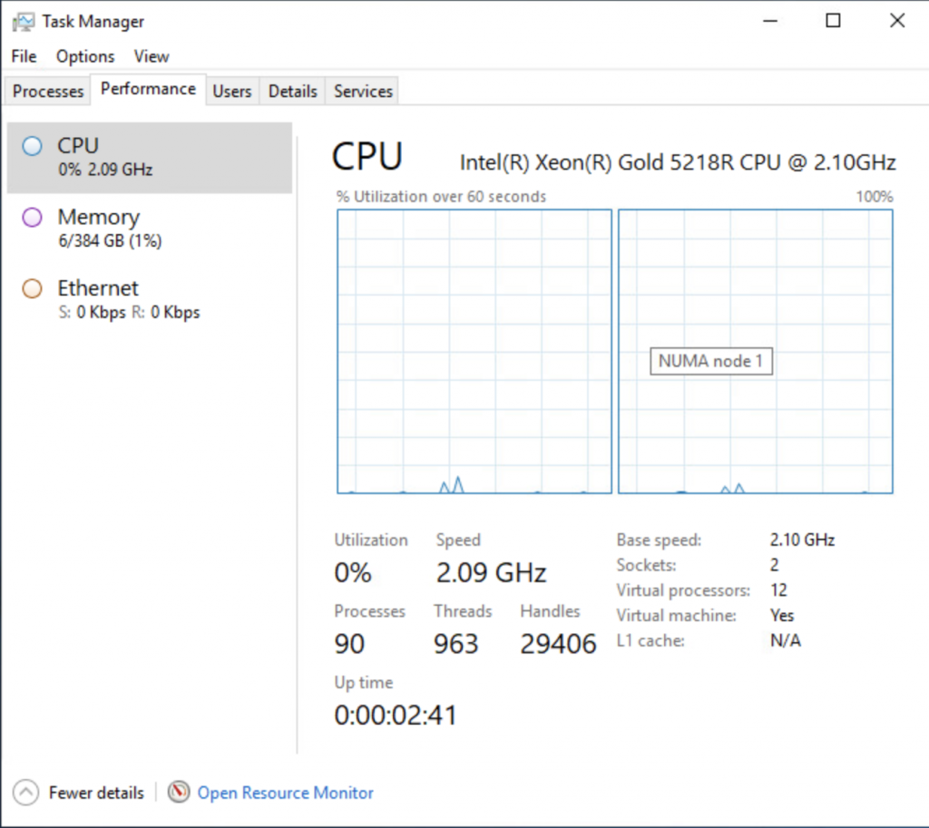
To check if everything has worked, I looked at the task manager of windows and enabled the NUMA view, which now shows two NUMA nodes.

Running the memory test again on the virtual machine shows a different behavior at the ESXi level. Memory consumption is far more balanced. The VMs NUMA client on NUMA node 0 is consuming 192 GB (201326592 KB), while the NUMA client of the VM on NUMA node 1 is consuming 189 GB (198604800 KB).

The vSphere 8 vCPU topology is a very nice method of helping manage VM configurations that are special cases. Instead of having to set advanced settings, a straightforward UI that can be easily understood by any team member that wasn’t involved with configuring the VM is a big step forward. But I like to stress once more that the default setting is the best for most virtual machines. Do not use this setting in your standard configuration for your virtual machine real estate. Keep it set to default and enjoy our 20 years of NUMA engineering. We got your back most of the time. And for some of the outliers, we now have this brilliant UI.

Filed Under: NUMA, Uncategorized

CPU pinning is not an exclusive right to a CPU core!

June 11, 2021 by frankdenneman

People who configure CPU Affinity deserve a special place in hell.. pic.twitter.com/wIIZ0dHDRw

— Katarina Brookfield (@MrsBrookfield) June 10, 2021

Katarina tweeted a very expressive tweet about her love/hate (mostly hate) relation with CPU pinning, and lately I have been in conversations with customers contemplating whether they should use CPU pinning.

The analogy that I typically use to describe CPU pinning is the story of the favorite parking space at your office parking lot. CPU pinning limits the compliant CPU “slots” for that vCPU to be scheduled on. So think about that CPU slot as the parking spot closest to the entrance of your office. You have decided that you only want to park in that spot. Every day of the year, that’s your spot and no other place else. The problem is, this is not a company-wide directive. Anyone can park in that spot, but you just limited yourself to that spot only. So it can happen that Bob arrives at the office first and lazy as he is, he will park to the office entrance as close as he can. Right in your spot. Now the problem with your self-imposed rule is that you cannot and will not park anywhere else. So when you show up (late to the party), you notice that Bob’s car is in YOUR parking spot, and the only thing you can do is to drive circles in some holding pattern until Bob leaves the office again. The stupidest thing. It’s Sunday, and you and Bob are the only ones doing some work. You’re out there on the parking lot, driving circles waiting until Bob leaves again, while Bob is inside in the empty building waiting on you to get started.

CPU pinning is not an exclusive right for that vCPU to use that particular CPU slot (Core or HT). It’s just a self-imposed limitation. If you want exclusive rights to a full core, check out the setting Latency Sensitivity

Filed Under: Uncategorized

vSphere with Tanzu vCenter Server Network Configuration Overview

November 6, 2020 by frankdenneman

I noticed quite a few network-related queries about the install of vSphere with Tanzu together with vCenter Server Networks (Distributed Switch and HA-Proxy).

The whole install process can be a little overwhelming when it’s your first time dealing with Kubernetes and load-balancing services. Before installing Workload Management (the user interface designation for running Kubernetes inside vSphere), you have to setup HA-Proxy, a virtual appliance for provisioning load-balancers.

Cormac did a tremendous job describing the configuration steps of all components. Still, when installing vSphere with Tanzu, I found myself mapping out the network topology to make sense of it all since there seems to be a mismatch of terminology between HA-proxy and Workload Management configuration workflow.

To help you navigate this diagram, I’ve provided annotations of the actual UI install steps. In total, three networks can be used for this platform;

NetworkMain Purpose
Management Communicating with vCenter, HA Proxy
WorkloadIP addresses for Kubernetes Nodes
FrontendVirtual IP range for Kubernetes clusters

You can use the same network for the workload and frontend but be sure you are using IP-ranges that do not overlap. Also, do not use a DHCP range on that network. I wasted two days figuring out that this was not a smart thing to do. The supervisor VMs are dual-homed and connect to the management network and the workload network. The frontend network contains the virtual IP range assigned to the kubernetes clusters, which can be the supervisor cluster and the TKG clusters.

To make it simple, I created three distinct VLANs with each their own IP-range:

Network IP Range VLAN
Management network 192.168.115/24 115
Workload network 192.168.116/24 116
Frontend network 192.168.117/24 117

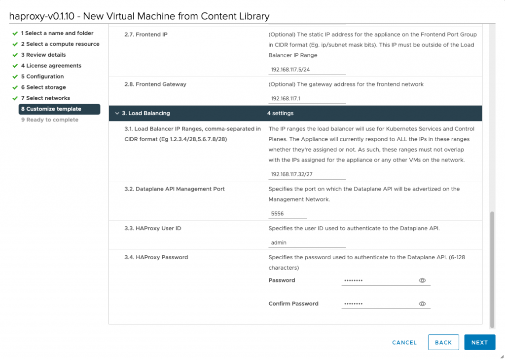
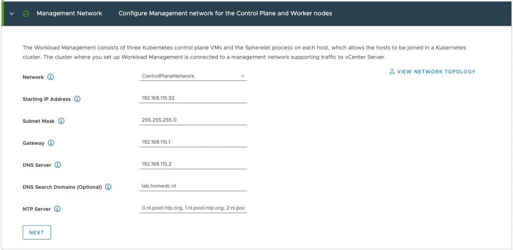
This overview can help you with mapping the ip-addresses used in the screenshot to the network designations in the diagram. For example, during the HA-Proxy install, you have to configure the network. This is step 2 of this process and step 2.3 requests the management IP of the HA Proxy virtual appliance.

HA-Proxy requires you to provide a load balancer IP range, that is used to provide a Kubernetes cluster a virtual IP.

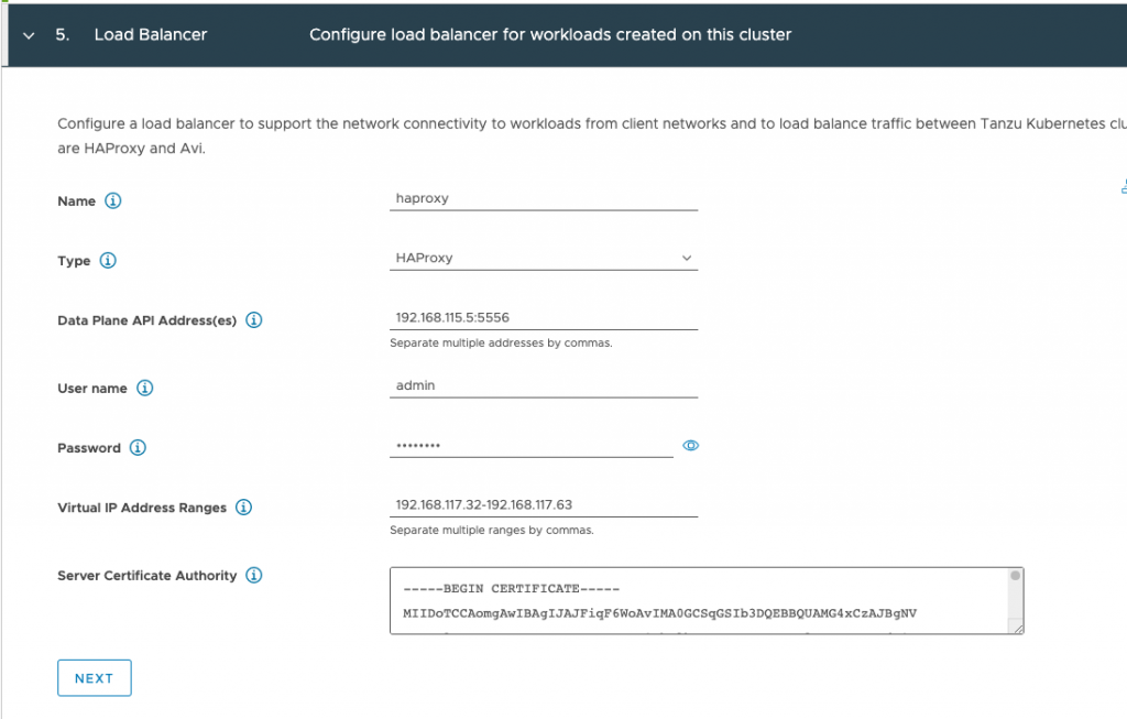
The next stop is workload management. In step 5, the first IP-address that you need to supply is the management IP address which you provided in step 2.3 of the HA-Proxy config process.

Staying on same config page, you need to provide the IP ranges for virtual servers, those are the ip-address defined in the frontend network. It’s the exact same range you used when configuring step 3.1 of the HA-proxy configuration process, but this time you have to write it out instead of using a CIDR format (Let’s keep you sharp! 😉 )

Step 6 of the workload management config process requires you to specify the IP addresses of the supervisor control plane VMs on the management network.

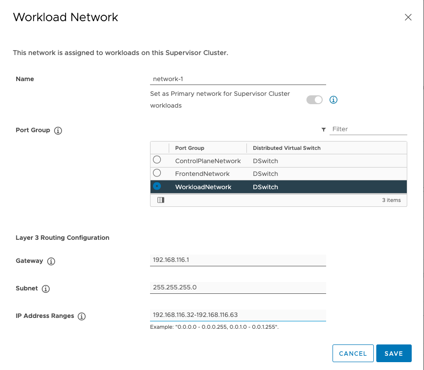
And the last network related configuration option, is step 7 in which you define the Kubernetes node IP range, this applies to both the supervisor cluster as well as the guest TKG clusters. This range is defined in the workload network portion in the top part the screen:

Click on add to open workload network config screen.

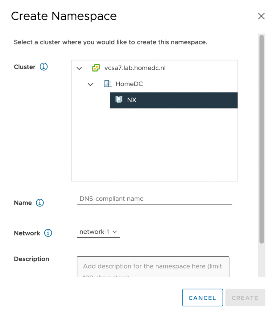
Tip, the network name you provide is presented to you when configuring a namespace for a workload within the vSphere\supervisor cluster. Please provide a meaningful name other than network-1

I hope this article helps you to wrap your head around these network requirements a little bit better. Please follow the instructions laid out in Cormacs Blog series and refer to these sets of diagram to get some visual aid in the process.

Filed Under: Uncategorized

  • Page 1
  • Page 2
  • Page 3
  • Interim pages omitted …
  • Page 9
  • Go to Next Page »

Copyright © 2025 · SquareOne Theme on Genesis Framework · WordPress · Log in