• Skip to primary navigation
  • Skip to main content

frankdenneman.nl

  • AI/ML
  • NUMA
  • About Me
  • Privacy Policy

Archives for 2015

DB Deepdive part 6: Query Plans, Intermediate Results, tempdb and Storage Performance

April 9, 2015 by frankdenneman

Welcome to part 6 of the Database workload characteristics series. Databases are considered to be one of the biggest I/O consumers in the virtual infrastructure. Database operations and database design are a study upon themselves, but I thought it might be interested to take a small peak underneath the surface of database design land. I turned to our resident Database expert Bala Narasimhan, PernixData’s VP of products to provide some insights about the database designs and their I/O preferences.
Previous instalments of the series:
Part 1 – Database Structures
Part 2 – Data pipelines
Part 3 – Ancillary structures for tuning databases
Part 4 – NoSQL platforms
Part 5 – Query Execution Plans
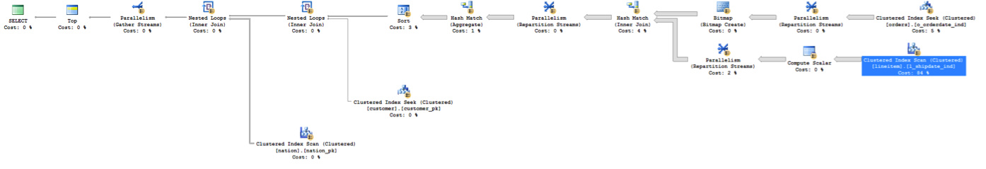
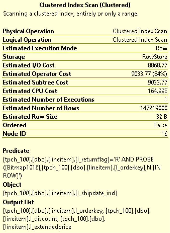
In a previous article I introduced the database query optimizer and described how it works. I then used a TPC-H like query and the SQL Server database to explain how to understand the storage requirements of a query via the query optimizer.
In today’s article we will deep dive into a specific aspect of query execution that severely impacts storage performance; namely intermediate results processing. For today’s discussion I will use the query optimizer within the PostgreSQL database. The reason I do this is because I want to show you that these problems are not database specific. Instead, they are storage performance problems that all databases run into. In the process I hope to make the point that these storage performance problems are best solved at the infrastructure level as opposed to doing proprietary infrastructure tweaks or rewrites within the database.
After a tour of the PostgreSQL optimizer we will go back to SQL Server and talk about a persistent problem regarding intermediate results processing in SQL Server; namely tempdb. We’ll discuss how users have tried to overcome tempdb performance problems to date and introduce a better way.
What are intermediate results?
Databases perform many different operations such as sorts, aggregations and joins. To the extent possible a database will perform these operations in RAM. Many times the data sets are large enough and the amount of RAM available is limited enough that these operations won’t fully fit in RAM. When this happens these operations will be forced to spill to disk. The data sets that are written to and subsequently read from disk as part of executing operations such as sorts, joins and aggregations are called intermediate results.
In today’s article we will use sorting as an example to drive home the point that storage performance is a key requirement for managing intermediate results processing.
The use case
For today’s example we will use a table called BANK that has two columns ACCTNUM and BALANCE. This table tracks the account numbers in a bank and the balance within each account. The table is created as shown below:
Create Table BANK (AcctNum int, Balance int);
The query we are going to analyze is one that computes the number of accounts that have a given balance and then provides this information in ascending order by balance. This query is written in SQL as follows:
Select count(AcctNum), Balance from BANK GROUP BY Balance ORDER BY Balance;
The ORDER BY clause is what will force a sort operation in this query. Specifically we will be sorting on the Balance column. I used the PostgreSQL database to run this query.
I loaded approximately 230 million rows into the BANK table. I made sure that the cardinality of the Balance column is very high. Below I have a screenshot from the PostgreSQL optimizer for this query. Note that the query will do a disk based merge sort and will consume approximately 4 GB of disk space to do this sort. A good chunk of the query execution time was spent in the sort operation.
part 6
A disk-based sort, and other database operations that generate intermediate results, is characterized by large writes of intermediate results followed by reads of those results for further processing. IOPS is therefore a key requirement.
What is especially excruciating about the sort operation is that it is a materialization point. What this means is that the query cannot make progress until the sort is finished. You’ve essentially bottlenecked the entire query on the sort and the intermediate results it is processing. There is no better validation of the fact that storage performance is a huge impediment for good query times.
What is tempdb?
tempdb is a system database within SQL Server that is used for a number of reasons including the processing of intermediate results. This means that if we run the query above against SQL Server the sorting operation will spill intermediate results into tempdb as part of processing.
It is no surprise then that tempdb performance is a serious consideration in SQL Server environments. You can read more about tempdb here.
How do users manage storage performance for intermediate results including tempdb?
Over the last couple of years I’ve talked to a number of SQL Server users about tempdb performance. This is a sore point as far as SQL Server performance goes. One thing I’ve seen customers do to remediate the tempdb performance problem is to host tempdb alone in arrays that have fast media, such as flash, in them in the form of either hybrid arrays or All Flash Arrays (AFA). The thought process is that while the ‘fast array’ is too expensive to standardize on, it makes sense to carve out tempdb alone from it. In this manner, customers look at the ‘fast array’ as a performance band aid for tempdb issues.
On the surface this makes sense since an AFA or a hybrid array can provide a performance boost for tempdb. Yet it comes with several challenges. Here are a few:

  • You now have to manage tempdb separately from all the other datastores for your SQL Server.
  • You procure the array for tempdb yet you do not leverage any of its data services. You use it as a performance band aid alone. This makes the purchase a lot more expensive than it seems on paper.
  • For queries that don’t leverage tempdb the array is not useful.
  • Performance problems in databases are not limited to tempdb. For example, you may be doing full table scans and these don’t benefit from the array.
  • You cannot leverage innovations in media. You cannot, for example, leverage RAM or PCM or anything else that will come in the future for tempdb.

How can PernixData FVP help?
In my mind PernixData FVP is the ideal solution for storage performance problems related to intermediate results in general and tempdb in particular. Intermediate result processing, including tempdb, shows very good temporal locality and is therefore an ideal candidate for FVP. Below are some other reasons why FVP is ideal for this scenario:

  • PernixData FVP allows you to use all server side media, flash or RAM, for accelerating tempdb and intermediate results processing.
  • You don’t need to configure anything separately for this. Instead you operate at the VM level and accelerate your database VM as a result of which every I/O operation is enhanced including intermediate results processing.
  • As your tempdb requirements change – lets say you need for space for handling it – it’s simply a matter of replacing one flash card with bigger one as far as FVP is concerned. There is no down time and the application is not impacted. This allows you to ride the price/performance curve of flash seamlessly.

Filed Under: Miscellaneous

Database workload characteristics and their impact on storage architecture design – part 5 – Query Execution Plans

April 7, 2015 by frankdenneman

Welcome to part 5 of the Database workload characteristics series. Databases are considered to be one of the biggest I/O consumers in the virtual infrastructure. Database operations and database design are a study upon themselves, but I thought it might be interested to take a small peak underneath the surface of database design land. I turned to our resident Database expert Bala Narasimhan, PernixData’s VP of products to provide some insights about the database designs and their I/O preferences.
Previous instalments of the series:
Part 1 – Database Structures
Part 2 – Data pipelines
Part 3 – Ancillary structures for tuning databases
Part 4 – NoSQL platforms
Databases are a critical application for the enterprise and usually have demanding storage performance requirements. In this blog post I will describe how to understand the storage performance requirements of a database at the query level using database tools. I’ll then explain why PernixData FVP helps not only to solve the database storage performance problem but also the database manageability problem that manifests itself when storage performance becomes a bottleneck. Throughout the discussion I will use SQL Server as an example database although the principles apply across the board.
Query Execution Plans
When writing code in a language such as C++ one describes the algorithm one wants to execute. For example, implementing a sorting algorithm in C++ means describing the control flow involved in that particular implementation of sorting. This will be different in a bubble sort implementation versus a merge sort implementation and the onus is on the programmer to implement the control flow for each sort algorithm correctly.
In contrast, SQL is a declarative language. SQL statements simply describe what the end user wants to do. The control flow is something the database decides. For example, when joining two tables the database decides whether to execute a hash join, a merge join or a nested loop join. The user doesn’t decide this. The user simply executes a SQL statement that performs a join of two tables without any mention of the actual join algorithm to use.
The component within the database that comes up with the plan on how to execute the SQL statement is usually called the query optimizer. The query optimizer searches the entire space of possible execution plans for a given SQL statement and tries to pick the optimal one. As you can imagine this problem of picking the most optimal plan out of all possible plans can be computationally intensive.
SQL’s declarative nature can be sub-optimal for query performance because the query optimizer might not always pick the best possible query plan. This is usually because it doesn’t have full information regarding a number of critical components such as the kind of infrastructure in place, the load on the system when the SQL statement is run or the properties of the data. . One example of where this can manifest is called Join Ordering. Suppose you run a SQL query that joins three tables T1, T2, and T3. What order will you join these tables in? Will you join T1 and T2 first or will you join T1 and T3 first? Maybe you should join T2 and T3 first instead. Picking the wrong order can be hugely detrimental for query performance. This means that database users and DBAs usually end up tuning databases extensively. In turn this adds both an operational and a cost overhead.
Query Optimization in Action
Let’s take a concrete example to better understand query optimization. Below is a SQL statement from a TPC-H like benchmark.
select top 20 c_custkey, c_name, sum(l_extendedprice * (1 - l_discount)) as revenue, c_acctbal, n_name, c_address, c_phone, c_comment from customer, orders, lineitem, nation where c_custkey = o_custkey and l_orderkey = o_orderkey and o_orderdate >= ':1' and o_orderdate < dateadd(mm,3,cast(':1'as datetime)) and l_returnflag = 'R' and c_nationkey = n_nationkey group by c_custkey, c_name, c_acctbal, c_phone, n_name, c_address, c_comment order by revenue;
The SQL statement finds the top 20 customers, in terms of their effect on lost revenue for a given quarter, who have returned parts they bought.
Before you run this query against your database you can find out what query plan the optimizer is going to choose and how much it is going to cost you. Figure 1 depicts the query plan for this SQL statement from SQL Server 2014 [You can learn how to generate a query plan for any SQL statement on SQL Server at https://msdn.microsoft.com/en-us/library/ms191194.aspx.
nested
You should read the query plan from right to left. The direction of the arrow depicts the flow of control as the query executes. Each node in the plan is an operation that the database will perform in order to execute the query. You’ll notice how this query starts off with two Scans. These are I/O operations (scans) from the tables involved in the query. These scans are I/O intensive and are usually throughput bound. In data warehousing environments block sizes could be pretty large as well.
A SAN will have serious performance problems with these scans. If the data is not laid out properly on disk, you may end up with a large number of random I/O. You will also get inconsistent performance depending on what else is going on in the SAN when these scans are happening. The controller will also limit overall performance.
The query begins by performing scans on the lineitem table and the orders table. Note that the database is telling what percentage of time it thinks it will spend in each operation within the statement. In our example, the database thinks that it will spend about 84% of the total execution time on the Clustered Index Scan on lineitem and 5% on the other. In other words, 89% of the execution time of this SQL statement is spent in I/O operations! It is no wonder then that users are wary of virtualizing databases such as these.
You can get even more granular information from the query optimizer. In SQL Server Management Studio, if you hover your mouse over a particular operation a yellow pop up box will appear showing very interesting statistics. Below is an example of data I got from SQL Server 2014 when I hovered over the Clustered Index Scan on the lineitem able that is highlighted in Figure 1.
fig2
Notice how Estimated I/O cost dominates over Estimated CPU cost. This again is an indication of how I/O bound this SQL statement is. You can learn more about the fields in the figure above here.
An Operational Overhead
There is a lot one can learn about one’s infrastructure needs by understanding the query execution plans that a database generates. A typical next step after understanding the query execution plans is to tune the query or database for better performance. For example, one may build new indexes or completely rewrite a query for better performance. One may decide that certain tables are frequently hit and should be stored on faster storage or pinned in RAM. Or, one may decide to simply do a complete infrastructure rehaul.
All of these result in operational overheads for the enterprise. For starters, this model assumes someone is constantly evaluating queries, tuning the database and making sure performance isn’t impacted. Secondly, this model assumes a static environment. It assumes that the database schema is fixed, it assumes that all the queries that will be run are known before hand and that someone is always at hand to study the query and tune the database. That’s a lot of rigidity in this day and age where flexibility and agility are key requirements for the business to stay ahead.
A solution to database performance needs without the operational overhead
What if we could build out a storage performance platform that satisfies the performance requirements of the database irrespective of whether query plans are optimal, whether the schema design is appropriate or whether queries are ad-hoc or not? One imagines such a storage performance platform will completely take away the sometimes excessive tuning required to achieve acceptable query performance. The platform results in an environment where SQL is executed as needed by the business and the storage performance platform provides the required performance to meet the business SLA irrespective of query plans.
This is exactly what PernixData FVP is designed to do. PernixData FVP decouples storage performance from storage capacity by building a server side performance tier using server side flash or RAM. What this means is that all the active I/O coming from the database, both reads and writes, whether sequential or random, and irrespective of block size is satisfied at the server layer by FVP right next to the database. You are longer limited by how data is laid out on the SAN, or the controller within the SAN or what else is running on the SAN when the SQL is executed.
This means that even if the query optimizer generates a sub optimal query plan resulting in excessive I/O we are still okay because all of that I/O will be served from server side RAM or flash instead of network attached storage. In a future blog post we will look at a query that generates large intermediate results and explain why a server side performance platform such as FVP can make a huge difference.
Post originally appeared on ToddMace.io

Filed Under: Miscellaneous

Don’t backup. Go forward with Rubrik

March 24, 2015 by frankdenneman

Screen Shot 2015-03-24 at 16.51.59
Rubrik has set out to build a time machine for cloud infrastructures. I like the message as it shows that they are focused on bringing simplicity to the enterprise backup world. Last week I had the opportunity to catch up with them and they had some great news to share as they were planning to come out of stealth this week. And that day is today.
Rubrik platform
This time machine is delivered on a 2U commodity appliance that runs the Rubrik software. By installing this appliance you greatly reduce the number of machines that are necessary to provide backup and restore services today. Reducing the number of machines simplifies the infrastructure for architects and support, while the UI of Rubrik simplifies the day-to-day operations of the administrators.
User Interface
No agents are needed in the virtual datacenters to discover the workload and the user interface is centered on policy driven SLAs. Unfortunately I can’t show the user-interface, but trust me this is something you longed for a long time. Due to the pedigree of the co-founders it comes as no surprise that the Rubrik platform is fully programmable with REST API’s.
Typically moving to a new backup system introduces risk and cost. Learning curves are high, misconfigured backup configurations possibly risking data loss. Policy driven and the ability to use REST APIs ensure that the platform easily integrates in every environment. The policies are so easy to use that no training is necessary; this reduces the impact of transition to a new backup system. The low learning curve means that no countless hours are lost by figuring out how to safely backup your data, while the REST APIs allow advanced tech crews to integrate Rubrik in their highly automated service offerings.
Architecture
One thing that made me very happy to see is the Rubriks’ ability to “cloud-out” your data. Rubrik provides a gateway to AWS allowing you to send “aged data” to the cloud in a very secure way. This feature benefits the complexity reduction of local architecture. Instead of having to incorporate a tape library, you now only need an Internet connection. Having worked with a big tape libraries myself for years I know this will not only bring a lot of datacenter space back and reduce your energy bill, you WILL have way less heat to cool.
As the team understand the concept of distributed architectures thoroughly (more about that in the next paragraph) it doesn’t come as a surprise that it scales very well. The architecture can scale to 1000s of nodes. What’s interesting is that it can mount the snapshots directly on the Rubrik platform allowing virtual machines to run directly on the appliance. Think about the possibilities for development. Snapshot your current production workload and test your new code instantly without any impact on active services.
Rubrik starts off by supporting VMware vSphere and it makes sense to focus on the biggest market out there as a startup. But support for other hypervisors and cloud infrastructures (to cloud-out data) will follow.
I expect Rubrik to become a success, the product aligns with the todays enterprise datacenter requirements and the pedigree of the team is amazing. As mentioned before the co-founders have a very rich background in distributed systems, Arvind Jain was the founding Engineer of Riverbed and was a Distinguished Engineer at Google before co-founding the other three members. Interesting enough (for me at least) there are stong ties with PernixData. Prior to Rubrik, Bipul Sinha was a partner at LightSpeed before founding Rubrik. I had the great pleasure of talking to Bipul often, as he is the initial investor of PernixData. Funny enough I can recall a conversation where Bipul asked me on my view of the backup world. I believe boring and totally not sexy was my initial reply. Guess he is setting out to change that fast! The CTO of Rubrik, Arvind Nithrakashyap, worked at Oracle where he co-founded Oracle Exadata. The other Co-founder of Exadata is PernixData CEO Poojan Kumar. Last but certainly not least Soham Mazumdar, who worked at Google on the search engine and founded Tagtile.
As of today you can sign-up for the early access program. Go visit the website to read more and follow them on twitter.
Exciting times ahead for Rubrik! Don’t Backup. Go Forward!

Filed Under: Miscellaneous

Part 3 – Data path is not managed as a clustered resource

March 16, 2015 by frankdenneman

Welcome to part 3 of the Virtual Datacenter scaling problems with traditional shared storage series. Last week I published an article about the FAST presentation “A Practical Implementation of Clustered Fault Tolerant Write Acceleration in a Virtualized Environment”. Ian Forbes followed up with the question about the advantages of throughput and latency of host-to-host network versus a traditional SAN when both have similar network speeds.
Part 1: Intro
Part 2: Storage Area Network topology
IOPS distribution amongst ESXi hosts
In the previous part of this series the IOPS provided by the array were equally divided amongst the ESXi hosts. In reality given the nature of applications and their variance it’s the application demand that drives the I/O demand. And due to this I/O demand will not be equally balanced across all the host in the cluster.
The virtual datacenter is comprised of different resource layers each with components that introduce their own set of load balancing algorithms. Back in 2009 Chad published nice diagram depicting all the queues and buffers of a typical storage environment. Go read the excellent article “VMware I/O queues, micro bursting and multipathing”.
How can you ensure that the available paths to the array are load-balanced based on virtual machine demand and importance? Unfortunately for us today’s virtual datacenter lacks load balance functionality that clusters these different layers, reducing hotspots and optimally distributes workloads. Let’s focus on the existing algorithms currently available, and possibly present, in virtual datacenters around the world.
Part3-01-Load balancing algorithms v2
Clustered load balancers
The only cluster-wide load balancing tools are DRS and Storage DRS. Both cluster resources into seamless pools and distribute workload according to their demand and their priority. When the current host cannot provide the entitled resources a virtual machine demands, the virtual machine is migrated to another host or datastore. DRS aggregates CPU and memory resources, Storage DRS tries to mix and match the VM I/O & capacity demand with the datastore I/O and capacity availability.
The layers between compute and datastores are equally important yet network bandwidth and data paths are not managed as a clustered resource. Load balancing occurs within the boundaries of the host; specifically they focus on outgoing data streams.
Data Path load balancing
With IP-based storage networks, multiple options exist to balance the workload across the outgoing ports. With iSCSI, binding of multiple VMkernel NICs can be used to distribute workload, some storage vendors prefer a configuration using multiple VLANS to load balance across storage ports. When using NFS Load Based Teaming (LBT) can be used to load balance data across multiple NICs.
Unfortunately all these solutions don’t take the path behind the first switch port in consideration. Although the existing workload is distributed across the available uplinks as efficiently as possible, no solution exists that pools the connected paths of the hosts in the cluster and distribute the workloads across the hosts accordingly. A solution that distributes virtual machines across host with less congested data paths in a well-informed and automatic manner simply does not exist.
Distributed I/O control
Storage I/O Control (SIOC) is a datastore-wide scheduler, allowing distributing of queue priority amongst the virtual machines located on various hosts that are connected to that datastore. SIOC is designed to deal with situations where contention occurs. If necessary it divides the available queue slots across the hosts to satisfy the I/O requirements based on the virtual machine priority. SIOC measures the latency from the (datastore) device inside the kernel to disk inside the array. It is not designed to migrate virtual machines to other hosts into the cluster to reduce latency or bandwidth limitations incurred by the data path. Network IO Control (NetIOC) is based on similar framework. It allocates and distributes bandwidth across the virtual machines that are using the NICs of that particular host. It has no ability to migrate virtual machines by taking lower utilized links of other hosts in the cluster into account.
Multipathing software
VMware Pluggable Storage Architecture (PSA) is interesting. The PSA allows third party vendors to provide their own native multipathing software (NMP). Within the PSA, Path Selection Plugins (PSPs) are active that are responsible for choosing a physical path for I/O requests. The VMware Native Multipathing Plugin framework supports three types of PSPs; Most Recently Used (MRU), Fixed and Round Robin. The Storage Array Type Plugins (SATP) run in conjunction with NMP and manages array specific operations. SATPs are aware of storage array specifics, such as whether it’s an active/active array or active/passive array. For example, when the array uses ALUA (Asymmetric LUN Unit Access) it determines which paths lead to the ports of the managing controllers.
The Round Robin PSP distributes I/O for a datastore down all active paths to the managing controller and uses a single path for a given number of I/O operations. Although it distributes workload across all (optimized) paths, it does not guarantee that throughput will be constant. There is no optimization on the I/O profile of the host. Its load balance algorithm is based purely on equal numbers of I/O down a given path, without regard to what the block size of I/O type is, it will not be balanced on application workload characteristics or the current bandwidth utilization of the particular path. Similar to SIOC and NetIOC, NMP is not designed to treat data paths as clustered resource and has no ability to distribute workloads across all available uplinks in the cluster.
EMC PowerPath is a third party NMP and has multiple algorithms that consider current bandwidth consumption of the paths and the pending types of I/O. It also integrates certain storage controller statistics to avoid negative affects by continuously switching paths. PowerPath squeezes as much performance (and resilience) out of their storage paths as possible because it can probe the link from host all the way to the back-end of a supported array and make decisions about active links accordingly. However PowerPath hosts do not communicate with each other and balances the I/O load on a host-by-host basis. This paragraph focuses on EMC solution; other storage vendors are releasing their NMP software with similar functionality. However not all vendors are providing their own software, and EMC PowerPath is only supported on a short list of storage vendors other than EMC own products.
Quality of Services on data paths
Quality of Services on data paths (QoS) is an interesting solution if it provides end-to-end QoS; from virtual machine to datastore. The hypervisor is context-rich environment, allowing kernel services to understand which I/O belongs to which virtual machine. However when the I/O exits the host and hits the network, the remaining identification is the address of the transmitting device of the host. There is no differentiation of priority possible other then at host level. Not all applications are equally important to the business, therefor end-to-end QoS is necessary to guarantee that business critical application get the resources they deserve. Scalability limitation on storage controller ports influences the overall impact of QoS. Similar to most algorithms, it does not aim to provide a balanced utilization of all available data paths; it deals with priority control during resource contention.
Storage Array layer
Storage DRS is able to migrate virtual machine files based on their resource demand. Storage DRS monitors the VMobserved latency, this includes the kernel and data path latency. Storage DRS incorporates the latency to calculate the benefit a migration has on the overall change in latency at source and destination datastore. It does not use the different latencies of kernel and data path to initiate a migration at compute level. Storage DRS initiates a self-vMotion to load the new VMX file as it has a different location after the storage vMotion, the virtual machine remains on the same hosts. In other words Storage DRS is not designed to migrate virtual machine at the compute layer or datastore layer to solve bandwidth imbalance.
Most popular arrays provide asymmetric LUN unit access. All ports on the Storage controllers accept incoming read and write operations, however the controller owning the LUN always manages read operations. Distributing LUNs across controllers are crucial as imbalance of CPU utilization or port utilization of the storage controllers can be easily introduced. LUNs can be manually transferred to improve CPU utilization, however this is not done dynamically unfortunately. Manual detection and management is as good as people watching it and not many organizations watch the environment at that scrutiny level all the time. Some might argue that arrays transfer the LUNs automatically, but that’s when a certain amount of “proxy reads” are detected. This means that the I/O’s are transmitted across the non-optimized paths, and likely either the PSP is not doing a great job, or all your active optimized paths are dead. Both not hallmarks of an healthy – or –properly architected environment.
Is oversizing a solution?
Oversizing bandwidth can help you so far, as its difficult to predict workload increase and intensity variation. Introduction of radically new application landscape impact current designs tremendously. When looking at the industry developments, its almost certain that most datacenters will be forced to absorb these new application landscapes, can current solutions applied in a traditional storage stack provide and guarantee the services they require and are they able to scale to provide the resources necessary?
Non-holistic load balancer available
In essence, the data-path between the compute layer and datastore layer is not treated as a clustered resource. Virtual machine host placement is based on compute resource availability and entitlement, disregarding the data path towards storage layer. This can potentially lead to hotspots inside the cluster, where some hosts saturate their data paths, while data paths of other hosts are underutilized. Data path saturation impacts application performance.
Unfortunately there is no mechanism available today that takes the various resource demands of a virtual machine into account. No solution at this time has the ability to intelligently manage these resources without creating other bottlenecks or impracticalities.
This article is not a stab at the current solutions. It is a very difficult problem to solve, especially for an industry that relies on various components of various vendors, expecting everything to integrate and perform optimally aligning. And think about moving forward and attempt to incorporate new technology advancements from all different vendors when they are available. And don’t forget about backward compatibility, world peace might be easier to solve.
With this problem in mind, the existence of uncontrollable data paths, oversubscribed inter-switch links and its inability to be application aware, many solutions nowadays move away from the traditional storage architecture paradigm. Deterministic performance delivery and Policy-driven management are the future and when no centralized control plane is available that stitching these disparate components together a different architecture arises. PernixData FVP, VMware VSAN and Hyper-converged systems rely on point-to-point network architectures of the crossbar switch architecture to provide consistent and non-blocking network performance to cater their storage performance and storage service resiliency needs.
Leveraging point-to-point connections and being able to leverage the context-aware hypervisor allows you not only to scale easily, it allows you to create environments that provide consistent and deterministic performance levels. The future datacenter is one step closer!
Part 4 focusses on the storage controller architecture and why leveraging host-to-host communication and host resource availability remove scalability issues.

Filed Under: Storage

Virtual Datacenter scaling problems with traditional shared storage – part 2

March 12, 2015 by frankdenneman

Oversubscription Ratios
The most common virtual datacenter architecture consists of a group of ESXi hosts connected via a network to a centralized storage array. The storage area network design typically follows the core-to-edge topology. In this topology a few high-capacity core switches are placed in the middle this topology. ESXi hosts are sometimes connected directly to this core switch but usually to a switch at the edge. An inter-switch link connects the edge switch to the core switch. Same design applies to the storage array; it’s either connected directly to the core switch or to an edge switch.
Part-2-01-core-edge-switch
This network topology allows scaling out easily from a network perspective. Edge switches (sometimes called distribution switches) are used to extend the port count. Although core switches are beefy, there is however a limitation on the number of ports. And each layer in the network topology has its inherent roles in the design. One of the drawbacks is that Edge-to-Core topologies introduce oversubscription ratios, where a number of edge ports use a single connection to connect to a core port. Placement of systems begins to matter in this design as multiple hops increase latency.
To reduce latency the number of hops should be reduced, but this impacts port count (and thus number of connected hosts) which impacts bandwidth availability, as there are a finite amounts of ports per switch. Adding switches to increase port count brings you back to device placement problems again. As latency play a key role in application performance, most storage area network aim to be as flat as possible. Some use a single switch layer to connect the host layer to the storage layer. Let’s take a closer look on how scale out compute and this network topology impacts storage performance:
Storage Area Network topology
This architecture starts of with two hosts, connected with 2 x 10GB to a storage array that can deliver 33K IOPS. The storage area network is 10GB and each storage controller has two 10GB ports. To reduce latency as much as possible, a single redundant switch layer is used that connects the ESXi hosts to the storage controller ports. It looks like this:
01-two host architecture
In this scenario the oversubscription ratio of links between the switch and the storage controller is 1:1. The ratio of consumer network connectivity to resource network connectivity is equal. New workload is introduced which requires more compute resources. The storage team increases the spindle count to increase more capacity and performance at the storage array level.
02-six host architecture
Although both the compute resources and the storage resources are increased, no additional links between the storage controllers are added. The oversubscription ratio is increased and now a single 10Gb link of an ESXi host has to share this link with potentially 5 other hosts. The answer is obviously increasing the number of links between the switch and the storage controllers. However most storage controllers don’t allow scaling the network ports. This design stems from the era where storage arrays where connected to a small number of hosts running a single application. On top of that, it took the non-concurrent activity into account. Not every application is active at the same time and with the same intensity.
The premise of grouping intermitted workloads led to virtualization, allowing multiple applications using powerful server hardware. Consolidation ratios are ever expanding, normalizing intermittent workload into a steady stream of I/O operations. Workloads have changed, more and more data is processed every day, pushing these IO’s of all these applications through a single pipe. Bandwidth requirements are shooting through the roof, however many storage area network designs are based of best practices prior to the virtualization era. And although many vendors stress to aim for a low oversubscription ratio, the limitation of storage controller ports prevents removing this constraint.
In the scenario above I only used 6 ESXi hosts, typically you will see a lot more ESXi hosts connected to the same-shared storage array, stressing the oversubscription ratio. In essence you have too squeeze more IO through a smaller funnel, this will impact latency and bandwidth performance.
Frequently scale-out problems with traditional storage architecture are explained by calculating the average number of IOPS per host by dividing the number of host by the total number of IOPS provided by the array. In my scenario, the average number of IOPS is 16.5K IOPS remained the same due to the expansion of storage resources at the same time the compute resources were added (33/2 or 100/6). Due to the way storage is procured (mentioned in part 1) storage arrays are configured for expected peak performance at the end of its life cycle.
When the first hosts are connected, bandwidth and performance are (hopefully) not a problem. New workloads lead to higher consolidation ratio’s, which typically result in expansion of compute cycles to keep the consolidation ratio at a certain level to satisfy performance and availability requirements. This generally leads to reduction of bandwidth and IOPS per hosts. Arguably this should not pose a problem if sizing was done correctly. Problem is, workload increase and workload behavior typically do not align with expectations, catching the architects off-guard or simply new application landscape turn up unexpectedly when business needs change. A lack of proper analytics impacts consumption of the storage resources and avoiding hitting limits. It’s not unusually for organizations to experience performance problems due to lack of proper visibility in workload behavior. To counteract this, more capacity is added to the storage array to satisfy capacity and performance requirements. However this does not solve the problem that exists right in the middle of these two layers. It ignores the funnel created by the oversubscription ratio of the links connected to the storage controller ports.
The storage controller port count impact the ability to solve this problem, another problem is that the way total bandwidth is consumed. The activity of the applications and the distribution of the virtual machines across the compute layer affect the storage performance, as workload might not be distributed equally across the links to the storage controllers. Part 3 of this series will focus on this problem.

Filed Under: VMware

  • « Go to Previous Page
  • Page 1
  • Page 2
  • Page 3
  • Page 4
  • Go to Next Page »

Copyright © 2025 · SquareOne Theme on Genesis Framework · WordPress · Log in