This is part 2 of the memory deep dive. This is a series of articles that I wrote to share what I learned while documenting memory internals for large memory server configurations. This topic amongst others will be covered in the upcoming FVP book. The memory deep dive series:
Part 1: Memory Deep Dive Intro
Part 2: Memory subsystem Organisation
Part 3: Memory Subsystem Bandwidth
Part 4: Optimizing for Performance
Part 5: DDR4 Memory
Part 6: NUMA Architecture and Data Locality
Part 7: Memory Deep Dive Summary
Today’s CPU micro-architectures contain integrated memory controllers. The memory controller connects through a channel to the DIMMs. DIMM stands for Dual Inline Memory Module and contains the memory modules (DRAM chips) that provide 4 or 8 bits of data. Dual Inline refers to pins on both side of the module. Chips on the DIMM are arranged in groups called ranks that can be accessed simultaneously by the memory controller. Within a single memory cycle 64 bits of data will be accessed. These 64 bits may come from the 8 or 16 DRAM chips depending on how the DIMM is organized.
An Overview of Server DIMM types
There are different types of DIMMs, registered and unregistered. Unregistered DIMM (UDIMM) type is targeted towards the consumer market and systems that don’t require supporting very large amounts of memory. An UDIMM allows the memory controller address each memory chip individually and in parallel. Each memory chip places a certain amount of capacitance on the memory channel and weakens the signal. As a result, a limited number of memory chips can be used while maintaining stable and consistent performance.
Servers running virtualized enterprise applications require a high concentration of memory. However with these high concentrations, the connection between the memory controller and the DRAM chips can overload, causing errors and delays in the flow of data. CPU speeds increase and therefor memory speeds have to increase as well. Consequently higher speeds of the memory bus leads to data flooding the channel faster, resulting in more errors occurring.
To increase scale and robustness, a register is placed between the DRAM chips and the memory controller. This register, sometimes referred to as a buffer, isolates the control lines between the memory controller and each DRAM chip. This reduced the electrical load, allowing the memory controller to address more DRAM chips while maintaining stability. Registered DIMMs are referred to as RDIMMs.
Load Reduced DIMMs (LRDIMMs) were introduced in the third generation of DDR memory (DDR3) and buffers both the control and data lines from the DRAM chips. This decreases the electrical load on the memory controller allowing for denser memory configurations. The increased memory capacity leads to increased power consumption, however by implementing the buffer structure differently it provides substantially higher operating data rates than RDIMMs in the same configuration.
The key to increased capacity and performance of LRDIMMs is the abstraction of DRAM chips and especially the rank count by the buffer. RDIMMs register only buffers the command and address while leaving the more important data bus unbuffered. This leaves the group of DRAM chips (ranks) exposed to the memory controller. A memory controller accesses the grouped DRAM chips simultaneously. A Quad rank DIMM configuration presents four separate electrical loads on the data bus per DIMM. The memory controller can handle up to a certain amount of load and therefor there is a limitation on the number of exposed ranks. LRDIMMs scale to higher speeds by using rank multiplication, where multiple ranks appear to the memory controller as a logical rank of a larger size.
DIMM Ranking
DIMMs come in three rank configurations; single-rank, dual-rank or quad-rank configuration, ranks are denoted as (xR). Together the DRAM chips grouped into a rank contain 64-bit of data. If a DIMM contains DRAM chips on just one side of the printed circuit board (PCB), containing a single 64-bit chunk of data, it is referred to as a single-rank (1R) module. A dual rank (2R) module contains at least two 64-bit chunks of data, one chunk on each side of the PCB. Quad ranked DIMMs (4R) contains four 64-bit chunks, two chunks on each side.
To increase capacity, combine the ranks with the largest DRAM chips. A quad-ranked DIMM with 4Gb chips equals 32GB DIMM (4Gb x 8bits x 4 ranks). As server boards have a finite amount of DIMM slots, quad-ranked DIMMs are the most effective way to achieve the highest memory capacity. As mentioned before there are some limitations when it comes to the amount of ranks used in a system. Memory controllers use channels to communicate with DIMM slots and each channel supports a limited amount of ranks due to maximal capacitance.
Memory Channel
Modern CPU microarchitectures support triple or quadruple memory channels. These multiple independent channels increases data transfer rates due to concurrent access of multiple DIMMs. When operating in triple-channel or in quad-channel mode, latency is reduced due to interleaving. The memory controller distributes the data amongst the DIMM in an alternating pattern, allowing the memory controller to access each DIMM for smaller bits of data instead of accessing a single DIMM for the entire chunk of data. This provides the memory controller more bandwidth for accessing the same amount of data across channels instead of traversing a single channel when it stores all data in one DIMM.
If the CPU supports triple-channel mode, it is enabled when three identical memory modules are installed in the separate channel DIMM slots. If two of the three-channel slots are populated with identical DIMMs, then the CPU activates dual-channel mode. Quad-channel mode is activated when four identical DIMMs are put in quad-channel slots. When three matched DIMMs are used in Quad-channel CPU architectures, triple-channel is activated, when two identical DIMMs are used, the system will operate in dual-channel mode.
LRDIMM rank aware controllers
With the introduction of LRDIMMs, memory controllers have been enhanced to improve the utilization of the LRDIMMs memory capacity. Rank multiplication is of of these enhancements and improved latency and bandwidth tremendously.
Generally memory controllers of systems prior to 2012 were “rank unaware” when operating in rank multiplication mode. Due to the onboard register on the DIMM it was unaware whether the rank was on the same DIMM it had to account for time to switch between DRAMS on the same bus. This resulted in lower back-to-back read transactions performance, sometimes up to 25% performance penalty. Many tests have been done between RDIMMs and LRDIMMs operating at the same speed. In systems with rank unaware memory controllers you can see a performance loss of 30% when comparing LRDIMMs and RDIMMS.
Systems after 2012 are referred to generation 2 DDR3 platforms and contain controllers that are aware of the physical ranks behind the data buffer. Allowing the memory controller to adjust the timings and providing better back-to-back reads and writes. Gen 2 DDR3 systems reduce the latency gap between RDIMMs and LRDIMMs but most importantly it reduces the bandwidth gap. Please be aware of this difference when reading memory reviews posted on the net by independent hardware review sites. Verify the date of the publication to understand if they tested a configuration that was rank aware or rank unaware systems.
DDR4 LRDIMMs improves lantencies even further due to use of distributed data buffers. DDR4 memory is covered in the third article in this series.
Pairing DIMMs per Memory Channel
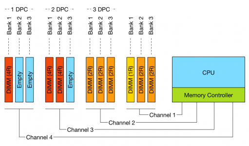
Depending on the DIMM slot configuration of the server board, multiple DIMMs can be used per channel. If one DIMM is used per channel, this configuration is commonly referred to as 1 DIMM Per Channel (1 DPC). 2 DIMMs per channel (2 DPC) and if 3 DIMMs are used per channel, this configuration is referred to as 3 DPC.

The diagram illustrates different DPC configurations; please note that balanced DIMM population (same number and type of DIMMs in each channel) is generally recommended for the best overall memory performance. The configuration displayed above is non-functional do not try to repeat.
However there are some limitations to channels and ranking. To achieve more memory density, higher capacity DIMMs are required. As you move up in the size of gigabytes of memory, you are forced to move up in the ranks of memory. For example single rank and dual rank RDIMMs have a maximum capacity per DIMM of 16GB. DDR3 32GB RDIMMs are available in quad rank (QR). Recently 64GB DIMS are made available, but only in LRDIMM format.
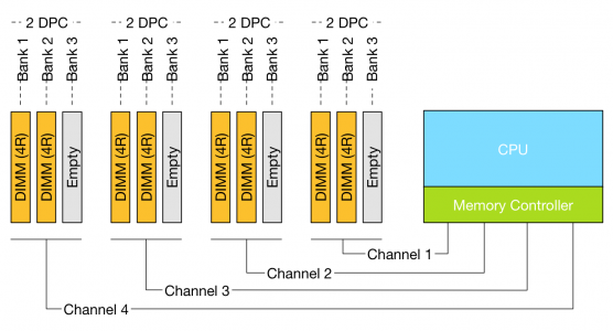
Memory rank impacts the number of DIMMS supported per channel. Modern CPUs can support up to 8 physical ranks per channel. This means that if a large amount of capacity is required quad ranked RDIMMs or LRDIMMs should be used. When using quad ranked RDIMMs, only 2 DPC configurations are possible as 3 DPC equals 12 ranks, which exceeds the 8 ranks per memory rank limit of currents systems.

When comparing 32GB LRDIMMs and 32GB Quad Rank RDIMMs it becomes apparent that LRDIMMS allow for higher capacity while retaining the bandwidth. For example, a Gen 12 Dell R720 contains two Intel Xeon E5 2600 CPU, allowing up to 1.5TB of RAM. The system contains 24 DIMM slots and allows up to 64GB DDR3 DIMMs up to 1866 Mhz. Dells memory configuration samples only contain configurations up to 1600 MHz.
Table 1: Total capacity configuration of RDIMMs and LRDIMMs
| DIMM Type | Capacity | Number of DIMMs | Ranking | Total capacity | Bandwidth |
| RDIMM | 16GB | 16 | 2R | 256GB | 1600MHz |
| RDIMM | 32GB | 16 | 4R | 512GB | 1333 MHz |
| LRDIMM | 32GB | 24 | 4R | 768GB | 1333MHz |
| LRDIMM | 64GB | 24 | 4R | 1536GB | 1333MHz |
Source: Online R720 manual
Source: Sample Memory configurations
Design consideration
DIMM types impact future expandability of the server. Due to the maximum of ranks support per channel, care must be taken when initially designing the server spec of the server.
Unfortunately, there is a downside when aiming for high memory capacity configurations and that is the loss of bandwidth. The interesting thing is when you increase DIMM count the bandwidth typically decreases. This impacts memory performance. The relationship between frequency and bandwidth is the topic of the next article in this series;
Up next, part 3: Memory Subsystem Bandwidth
The memory deep dive series:
Part 1: Memory Deep Dive Intro
Part 2: Memory subsystem Organisation
Part 3: Memory Subsystem Bandwidth
Part 4: Optimizing for Performance
Part 5: DDR4 Memory
Part 6: NUMA Architecture and Data Locality
Part 7: Memory Deep Dive Summary
Hi Frank, I’ve seen that the CAS latency is higher on DDR4 and that could be a concern for large memory workloads currently running on DDR3. Difference can be as much as 25%. Also there is a price delta at the moment. But I think that’ll change and 32GB will become the sweet spot per DIMM rather than the current 16GB sweet spot. Another observation is that it’s better to have more slower memory for DB workloads etc that need the RAM rather than using disk for reads and potentially swap. There are a lot of trade offs. I’d also like your views on the low voltage DIMMs.
Hi Michael,
Thanks for your comment. Think about DB’s in FVP DFTM. Even the slowest ram will outperform any disk. But since we’re talking about configuring and spec’ing servers, let optimise as much as possible. 🙂
DDR4 Cas Latency’s are a bit strange, although they appear higher, the difference might not be that severe as your stating.
Pricing of DDR4 is expected to drop after september, lets hope so as it provides a tremendous boost. The drop-off on bandwidth when using 2 or 3 DPC is reduced in DDR4. But I’ll cover that all in part 3.
Low voltage will be handled in the next part.
Hi Frank. Excellent blog post us always! I’m really looking forward for next part.