This article provides you an overview of the steps required to setup a Multi-NIC vMotion configuration on an existing distributed Switch with the vSphere 5.1 web client. This article is created to act as reference material for the designing your vMotion network series.
Configuring Multi-NIC vMotion is done at two layers, first the distributed switch layer where we are going to create two distributed port groups and the second layer is the host layer. At the host layer we are going to configure two VMkernel NICs and connect them to the appropriate distributed port group.
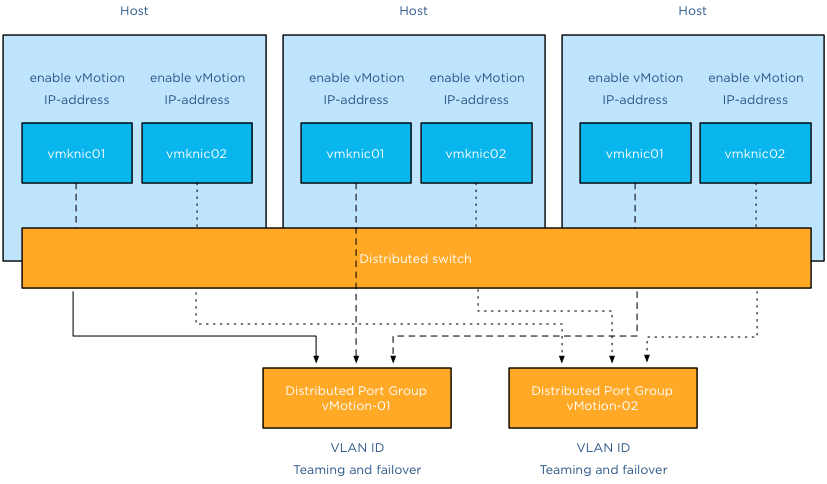
Before you start you need to have ready two ip-addresses for the VMkernel NICs, their respective subnet and their VLAN ID.
Distributed switch level
The first two steps are done at the distributed switch level, click on the networking icon in the home screen and select the distributed switch.
Step 1: Create the vMotion distributed port groups on the distributed switch
The initial configuration is pretty much basic, just provide a name and use the defaults:
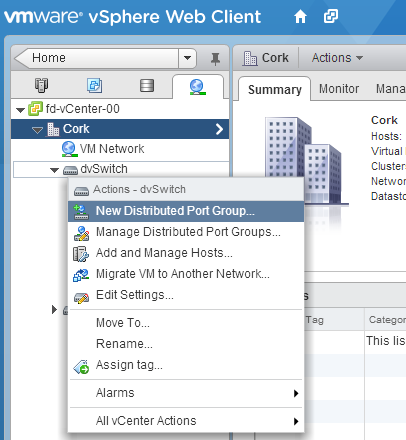
1: Select the distributed switch, right click and select “New Distributed Port Group”.
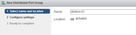
2: Provide a name, call it “vMotion-01” and confirm it’s the correct distributed switch.
3: Keep the defaults at Configure settings and click next.
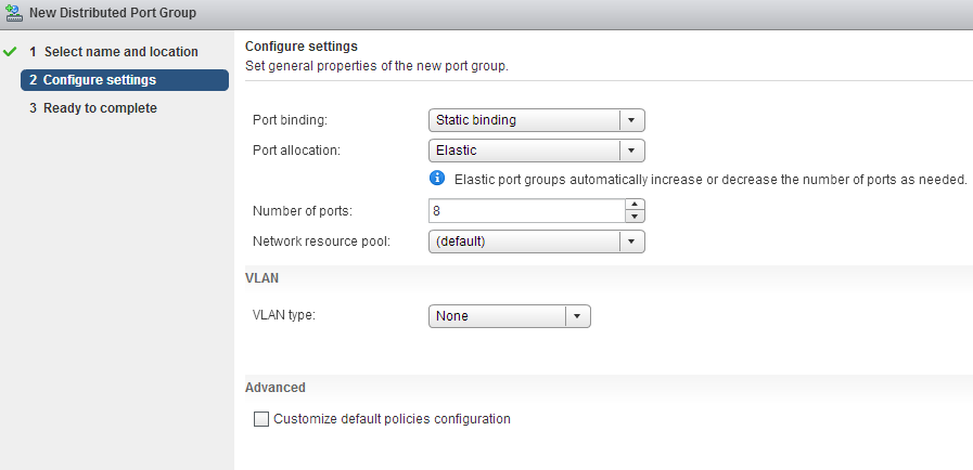
4: Review the settings and click finish.
Do the same for the second distributed port group, name that vMotion-02
Step 2: Configuring the vMotion distributed port groups
Configuring the vMotion distributed port groups consist of two changes. Enter the VLAN ID and set the correct failover order.
1: Select distributed Port Group vMotion-01 in the left side of your screen and right click and select edit settings.
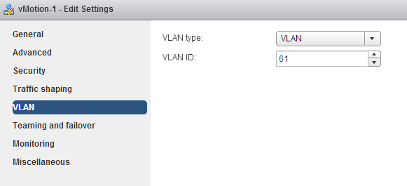
2: Go to VLAN, select VLAN as VLAN type and enter the first VLAN used by the first VMkernel NIC.
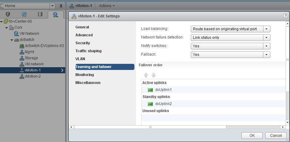
3: Select “Teaming and failover” , move the second dvUplink down to mark it as a “Standby uplink”. Verify that load balancing is set to “Route based on originating virtual port”.
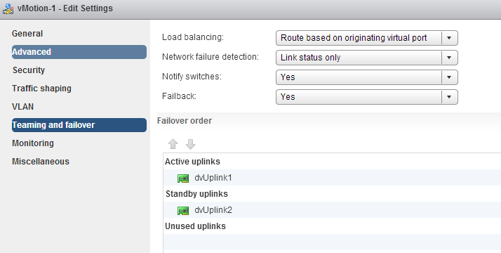
4: Click OK
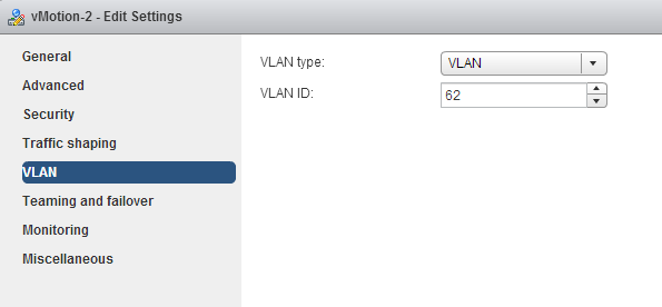
Repeat the instructions of step 2 for distributed Portgroup vMotion-02, but use the VLAN ID used by the IP-address of the second VMkernel NIC.
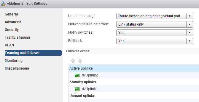
Go to teaming and failover and configure the uplinks in an alternate order, ensuring that the second vMotion VMkernel NIC is using dvUplink2.
Host level
We are done at the distributed switch level, the distributed switch now updates all connected hosts and each host has access to the distributed port groups. Two vMotion enabled VMkernel NICs are configured at host level. Go to Hosts and Clusters view.
Step 3: Create vMotion enabled VMkernel NICs
1: Select the first host in the cluster, go to manage, networking and “add host networking”.

2: Select VMkernel Network Adapter.

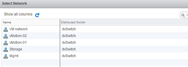
3: Select an existing distributed portgroup, click on Browse and select distributed Port Group “vMotion-01” Click on OK and click on Next.

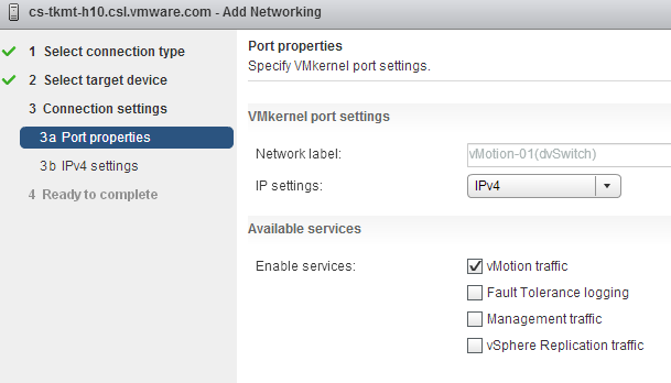
4: Select vMotion traffic and click on Next.
5: Select static IPv4 settings, Enter the IP-address of the first VMkernel NIC corresponding with the VLAN ID set on distributed Port Group vMotion-01.
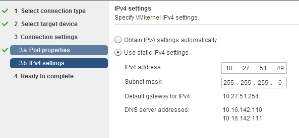
6: Click on next and review the settings.
Create the second vMotion enabled VMkernel NIC. Configure identically except:
1: Select vMotion-02 portgroup
2: Enter IP-address corresponding with the VLAN ID on distributed Port Group vMotion-02.
The setup of a Multi-NiC vMotion configuration on a single host is complete. Repeat Step 3 on each host in the cluster.
10 guidelines for creating good looking diagrams
Frequently I receive the question which application I use to create my diagrams. I used to use Microsoft Visio but starting to use Omnigraffle a year ago. However I feel it’s not the program that makes these diagrams. Although it’s true that some functionality help me to create the diagrams more easily, it’s more about following some basic guidelines. I’ve picked up these guidelines along the way, they work for me and hopefully they can help you too.
1: Find a suitable color scheme
A color scheme plays a very important role in a diagram. Colors have various functions within a diagram. I like to use various tints of a color to indicate a relation between objects, whether it has to indicate a relation within the same structure layer or the same consumer or provider. For example all storage related functions or objects have different shades of blue or resource pool structure of customer A have different shades of green.
Picking the correct color for a diagram is very difficult and trying to select the perfect collection of colors wasted (I should say invested) many hours of my life. During that time I learned a lot, here are a few tips:
- Use a color scheme that provides contrast between different objects.
- Use the wheel of color to easily select complimentary colors (Colors on opposite sides of the color wheels). I prefer using multiple triad (3-point) complement color schemes.
- When using multiple triads, uses colors of similar saturation levels. Saturation refers how a “color” appears under a particular lighting condition. Mixing primary and secondary colors with similar saturation levels provides a more cohesive looking design. For example, a bright red color mixed with a blue-ish green color can give some strange effects, sometimes giving the illusion of vibrating when not looking directly at them (very annoying).
- Use a limited set of colors, don’t allow your diagram to become the poster-child for circus publication guidelines.
Resources:
- Smashing magazine have published an excellent series on color theory
- colorschemedesiginer.com shows the Color wheel, use the triad function
2: Fonts
Besides legibility and readability a proper font (typeface) makes the diagram “look right”. Objects and fonts are interrelated when it comes to conveying a subject. Both the font type and the objects in the diagram translate and visualize an idea or concept. Colors evoke feelings and moods, while the font determine the tone of voice in which the message is broadcasted.
Two major categories of typefaces can be identified in the world of fonts. Serif and sans-serif. Serif fonts can be recognized by having small lines at the end of the strokes of a letter. Times new roman is a good example of a serif font. Serif fonts mimic handwriting and can provide a outdated but also formal feeling. Sans-serif fonts lack the small lines and provide a much cleaner and modern look. I have seen diagrams illustrating technologies and features that weren’t released yet, but still gave me an outdated, well-worn feeling. Try use sans-serif fonts when creating computer technology related diagrams.
- Use a sans-serif font (PT sans or corbel are excellent choices)
- Try to use a font that compliments the font used in the articles
- Use a single font in a diagram; use different font weights (light, medium, bold) to emphasize.
- Color contrast; use dark colors on white background, white on black background. Tip: dark blue on white gives a rich feeling to the labels.
- Use handwritten fonts only if you use hand drawn objects. Match font style with objects. Swooping lines as connectors allow for the use of a more elegant font, however keep it in style with your overall blog theme and used fonts.
- Do not use Comic sans, unless you are diagramming your lemonade stand!
Resources:
- Google fonts and myfonts.com provide an enormous font collection. Most of them can be downloaded for free.
- Use whatthefont service to identify a specific font used in an image.

3: Lines
Lines come in all shapes and forms. Try to be consistent with the types of lines you use. If you use a dashed line for indicating standby functionality, do not use the same line pattern for an active connection. Think about the thickness of the lines used. If you selected a very clean lightweight font, don’t use thick lines for the framework of boxes and other objects. Mix and match line weight with font weight. Strive for balance across the entire diagram.
4: Whitespace
Whitespace or often revered to as negative space is the portion of the diagram left unused. It’s the space between the objects and this is what I believe actually the most important thing to get right. The balance between the positive (objects) and the negative (whitespace) is fundamental to create an aesthetic pleasing diagram. Whitespace can help to emphasize particular elements but also help to balance the objects in the diagram. Using too much whitespace and a relationship between two objects may get lost.
5: Align!
Always align objects horizontally and if applicable vertically. These details matter. It might not be easily identified by eye, but your subconscious picks it up and alerts you “something is not right”. Most people tend to shy away and that’s conflicts the first reason why you made the diagram. To help people better understand the subject by creating additional visual aids. Omnigraffle is far more advanced than Visio when it comes to auto alignment. Omnigraffle provides automatic guides displaying the white space between objects in the same line. That feature saved me many hours
6: Go minimal
Try to reduce the number of objects as much as possible. Get to the essence of the subject as much as possible. IT people like to put in as much as detail as possible. If these objects are not relevant to the subject you are trying to depict, leave them out. This increases the focus point of the diagram. Going minimal is harder than it sounds. By using as little objects as possible you spend a lot time focusing on spacing, positioning, typography and contrast.
7: Shadows
The novelty of shadows beneath lines and boxes wear off quickly. After viewing the diagram a couple of times, the shadows give the diagram an unclean and grimy feeling. It doesn’t look clean, fresh and rapidly feels outdated after seeing the diagram a couple of times. My advice: Try to avoid it as much as possible.
8: Real men make block diagrams
Sometimes I jokily reply this when somebody is asking for vendor stencils and icon-packs on twitter. Vendor stencils can be very useful for some types of diagrams, for example wiring diagram of a core Ethernet switch. I prefer to stay away from using pre-made icons in diagrams indicating architecture or relationships. Pre made icons come in their own color scheme and are usually in an isometric perspective to give that 3d feel. Forcing you to design the whole diagram in an isometric perspective. Certain Icon designs distract the viewer, reducing the ability of the diagram to convey the message. By creating your own objects, you can choose your own color scheme, your own level of detail, and your own direction of perspective.
9: Commit to a single perspective
Already mentioned in the number 8, when using an icon in isometric perspective commit to drawing in an isometric perspective. The viewpoint of an isometric diagram is slightly rotated to reveal other surfaces than those visible from a top-down perspective. Isometric diagrams are a great way for illustrating all the physical components of (virtual) architectures. A while ago I stumbled upon an old isometric diagram I created for a client of mine. Mixing isometric icons with top-down icons provides an unbalanced view. Usually the lines do not connect well or are just to complete parallel or horizontally aligned, providing hours of frustration to the stickler for details.
10: Relevance
A picture is worth a thousand words, but don’t draw a giraffe after you wrote three paragraphs about the feeding habits of elephants. This is an extreme example, but use a diagram to help the reader to understand the aspect of the topic and assist him with the identification of the subject. Don’t allow a diagram to confuse your audience. I’ve seen countless diagrams in VCDX architecture designs of arrays connected to an FC architecture, when the candidate was using an iSCSI. If you use 6 LUNs, don’t use a diagram that shows an object with the words “LUN 1 …. LUN 99” in it. Allow the diagram relay information to strengthen the written word.
Be consistent and have fun
In almost all of the other guidelines I provide examples why consistency is important. It helps the reader to identify components and their relation more easily. Especially when you use a series of diagrams in the same presentation or publication. Do it well and allow it to become your trademark. But most of all have fun while creating diagrams. It shows!
Designing your vMotion network – 3 reasons why I use a distributed switch for vMotion networks
If your environment is licensed with the enterprise plus license you can choose to use a standard vSwitch or use a distributed switch for your vMotion network. Multi-NIC vMotion network is a complex configuration that consists out of many different components. Each component needs to be configured identically on each host in the cluster. Distributed switches can help you with that and in addition provide you with tools to prioritize traffic and allow other network streams to utilize available bandwidth when no vMotion traffic is active.
1. Use distributed portgroups consistent configuration across the cluster
Consistently configuring two portgroups on each host in the cluster with alternating vmnic failover order is a challenging task. It’s a mere fact that humans are not good in performing a repetitive task consistently. Many virtual infrastructure health checks at various sites confirmed that fact.
The beauty of distributed switches (VDS) is that it acts as profile configuration. Configure the portgroup once and the distributed switch propagates these settings to all the connected hosts of that distributed switch. A multi-NIC vMotion configuration is a perfect use-case to leverage the advantages of the distributed switch. As mentioned a Multi-NIC vMotion configuration is a complex configuration consisting of two portgroups with their own unique settings.
By using the distributed switch, only two distributed portgroups need to be configured and the VDS distributes the portgroups and their settings to each host connected to the VDS. This saves a lot of work and you are ensured that each host is using the same configuration. Consistency in your cluster is important for to provide you reliable operations and consistent performance.
2. Set traffic priority with Network I/O Control
Network I/O control can help you to consolidate the network connections into a single manageable switch, allowing you to utilize all the bandwidth available while still respecting requirements such as traffic isolation or traffic prioritization. This is applicable to both configurations containing a small number of 10GbE uplink as well for configurations that contain a high number of 1GbE ports.
vMotion has a high bandwidth usage, performing optimally in high bandwidth environments. However vMotion traffic is not always present. Isolating NICs in order to protect other network traffic streams or provide a particular level of bandwidth can be uneconomical and may leave bandwidth idle and unused.
By using Network I/O Control, you can control the priority of network traffic during contention. This allows you to specify the relative importance of traffic streams and provide bandwidth to particular traffic streams when other traffic competes for bandwidth.
3. Using Load Based Teaming to balance all traffic across uplinks
Load based teaming, identified in the user interface as “Route based on physical NIC load” allows for ingress and egress traffic balancing. When consolidating all uplinks in one distributed switch, load based teaming (LBT) distributes the traffic streams across the available uplinks by taking into the utilization into account.
Please note: Use Route based on originating virtual port load balancing policy for the two vMotion portgroup, but configure VM network with load based teaming load balancing policy. Route based on originating virtual port load balance policy creates a vNIC to pNIC relation during boot of a virtual machine. That vNIC is “bound” to that pNIC until the pNIC fails or the virtual machine is shutdown. When using a converged network or allowing all network traffic to use each uplink, a virtual machine could experience link saturation or latency due to vMotion using the same uplink. With LBT the virtual machine vNIC can be dynamically bound to a different pNIC with lesser utilization, providing better network performance. LBT monitors the utilization of each uplink and when the utilization is greater than 75 percent for a sustained period of time, LBT moves traffic to other underutilized uplinks.
The benefits of a Distributed vSwitch
Consistent configuration across hosts saves a lot effort, during configuration and troubleshooting. Consistent configuration is key when providing a stable and a performing environment. Multi-NIC vMotion allows you to use as much bandwidth as possible benefitting DRS in load balance and maintenance mode operations. LBT and Network I/O Control allow other network traffic streams to consume network traffic as much as possible. Load based teaming is a perfect partner to Network I/O Control. LBT attempts to balance out the network utilization across all available uplinks and Network I/O Control dynamically distributes network bandwidth during contention.
Back to standard vSwitch when uplink isolation is necessary?
Is this Multi-NIC vMotion/NetIOC/LBT configuration applicable to every customer? Unfortunately it isn’t. Converging all network uplinks into a single distributed switch and allowing all portgroups to utilize the uplinks require the VLANs to be available on every uplink. Some customers want to isolate vMotion traffic or other traffic and use dedicated links. For that scenario I would still use a distributed switch and create one for the vMotion configuration. In this particular scenario you do not leverage LBT and Network I/O Control but still benefit from the consistent configuration of distributed portgroups.
Part 1 – Designing your vMotion network
Part 2 – Multi-NIC vMotion failover order configuration
Part 3 – Multi-NIC vMotion and NetIOC
Part 4 – Choose link aggregation over Multi-NIC vMotion?
vMotion and EtherChannel, an overview of the load-balancing policies stack
After posting the article “Choose link aggregation over Multi-NIC vMotion” I received a couple of similar questions. Pierre-Louis left a comment that covers most of the questions. Let me use this as an example and clarify how vMotion traffic flows through the stack of multiple load balancing algorithms and policies:
A question relating to Lee’s post. Is there any sense to you to use two uplinks bundled in an aggregate (LAG) with Multi-NIC vMotion to give on one hand more throughput to vMotion traffic and on the other hand dynamic protocol-driven mechanisms (either forced or LACP with stuff like Nexus1Kv or DVS 5.1)?
Most of the time, when I’m working on VMware environment, there is an EtherChannel (when vSphere < v5.1) with access datacenter switches that dynamically load balance traffic based on IP Hash. If i'm using LAG, the main point to me is that load balancing is done independently from the embedded mechanism of VMware (Active/Standby for instance).
Do you think that there is any issue on using LAG instead of using Active/Standby design with Multi-NIC vMotion? Do you feel that there is no interest on using LAG over Active/Standby (from VMware point of view and for hardware network point of view)?
Pierre-Louis takes a bottom-up approach when reviewing the stack of virtual and physical load-balancing policies and although he is correct when stating that network load balancing is done independently from VMware’s network stack, it does not have the impact he thinks it has. Lets look at the starting point of vMotion traffic and how that impacts both the flow of packets and utilization of links. Please read the articles “Choose link aggregation over Multi-NIC vMotion” and “Designing your vMotion network” to review some of the requirements of Multi-NIC vMotion configurations
Scenario configuration
Lets assume you have two uplinks in your host, i.e. two physical NICs per ESX host. Each vmnic used by the VMkernel NIC (vmknic) is configured as active and both links are aggregated in a Link Aggregation Group (LAG) (EtherChannel in Cisco terms).
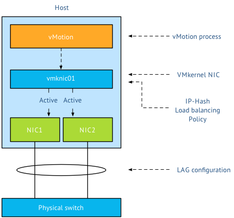
First thing I want to clarify that the active/standby state of a vmknic is static and is controlled by the user, not a Load-Balancing policy. When using a LAG, both vmknics need to be configured active, as the load balancing policy needs to be able to send traffic across both links. Duncan explains the impact when using Standby NICs in an IP-Hash configuration.
Load balancing stack
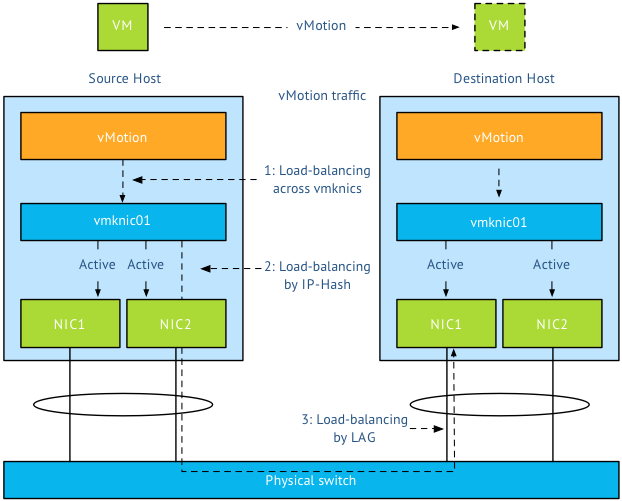
A vMotion is initiated on host-level; therefor the first load balancer that comes in to play is vMotion itself. Then the portgroup load balancing policy will make a decision followed by the physical switch. Load balancing done by the physical switch/LAG is the last element in this stack.
Step 1: vMotion load balancing, this is done on the application layer and it is vMotion process that selects which VMkernel NIC is used. As you are using a LAG and two NICs, only one vMotion VMkernel NIC should exist. The previous mentioned article explains why you should designate all vmnics as active in a LAG. By using one vmknic enabled for vMotion, vMotion is unable to load-balance at vmknic level and sends all the traffic to the single vmknic.
Step 2: Next step is the load-balancing policy; IP-Hash will select one NIC after it hashes both source and destination IP. That means that this vMotion operation will use the same NIC until the vMotion operation is complete. It does not use two links, as a vMotion operation connection is setup by two VMkernel NICs and thus two IP-addresses (source IP address and destination IP). As IP-Hash determines the vmknic, traffic will be send out across the physical link.
Step 3: is at the physical switch layer and determines which port to use to connect to a NIC of the destination host. Once the physical switch receives the packet, the load balancer of the LAG configuration comes into play. The physical switch determines which path to take to the destination host according to utilization or availability of a link. Each switch vendor has different types of load balancers, too many to describe, the article “Understanding EtherChannel Load Balancing and Redundancy on Catalyst Switches” describes the different load balancing operations within the Cisco Catalyst switch family.
In short:
Step 1 Load balancing by vMotion: has no direct control over which physical NICs are used, it load balances across available multiple vmknics.
Step 2 Load balancing by IP-HASH: Outgoing connection is hashed based on its source and destination IP address; hash is used to select a physical NIC to use for network transmissions.
Step 3 Load balancing by LAG: Physical switch connected to destination performs the hash to choose which physical NIC to send incoming connection to.
To LAG or not to LAG, that’s the question
By using a LAG configuration for vMotion traffic, you are limited to the available bandwidth of a single uplink per vMotion operation as only one uplink is used per vMotion operation. A Multi-NIC vMotion configuration balances vMotion traffic across both VMkernel NICs. It load balances traffic for a single vMotion operation as well as multiple concurrent vMotion operations across the links. Let me state that differently; It is able to use the bandwidth of two uplinks for both a single vMotion operation, as well as multiple vMotion operations. With Multi-NIC vMotion you will get a more equal load balance distribution than with any load-balancing policy operating at NIC level.
I would always select multi-NIC vMotion over LAG. A LAG requires strict configuration on both virtual level as physical level. It’s a complex configuration on both technical and political level. Multiple departments need to be involved and throughout my years as an architect I seen many infrastructures fail due to inter-department politics. Troubleshooting a LAG configuration is not an easy task in an environment where there are communication-challenges between the server and the network department. Therefor I strongly prefer not to use LAG in a virtual infrastructure
Multiple single uplinks can be used to provide more bandwidth to the vMotion process and other load-balancing policies available on the distributed switch keep track of link utilization (LBT). It’s less complex, and in most cases give you better performance.
Designing your vMotion networking – Choose link aggregation over Multi-NIC vMotion?
The “Designing your vMotion network” series have lead me to have some interesting conversations. A recurring question is why not use Link Aggregation technologies such as Etherchannel to increase bandwidth for vMotion operations. When zooming into vMotion load balancing operations and how the vNetwork load balancing operations work, it becomes clear that Multi-NIC vMotion network will provide a better performance that an aggregated link configuration.
Anatomy of vMotion configuration
In order to use vMotion a VMkernel network adapter needs to be configured. This network adapter needs to be enabled for vMotion and the appropriate load balancing policy and network adaptor failover mode needs to be selected.
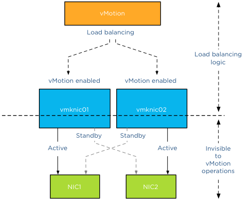
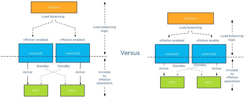
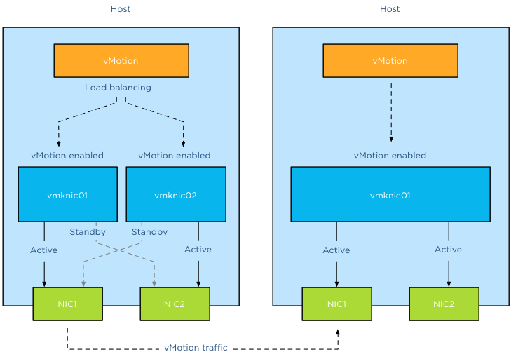
The vMotion load-balancing algorithm distribute vMotion traffic between the available VMkernel NICs, it does not consider the network configuration backing the VMkernel NIC (vmknic). vMotion expects that a vmknic is backed by a single active physical NIC, therefore when sending data to the vmknic the traffic will traverse a dedicated physical NIC. It’s important to understand that vMotion traffic flows between distinct vmknics! Migrating a virtual machine from a source host configured with Multi-NIC vMotion to a destination host with a single vmknic vMotion configuration result in the utilization of a single vmknic on the source host. Even though the single NIC vMotion is configured with two active uplinks, the source vMotion operation just selects one vmknic to transmit its data.
Link aggregation
My esteemed colleague Vyenkatesh “ Venky” Deshpande published an excellent article on the new LACP functionality on the vSphere blog. Let me highlight a very interesting section:
Link aggregation allows you to combine two or more physical NICs together and provide higher bandwidth and redundancy between a host and a switch or between two switches. Whenever you want to create a bigger pipe to carry any traffic or you want to provide higher reliability you can make use of this feature. However, it is important to note that the increase in bandwidth by clubbing the physical NICs depends on type of workloads you are running and type of hashing algorithm used to distribute the traffic across the aggregated NICs.
And the last part is the key, when you aggregate links into a single logical link, it depends on the load balancing / hashing algorithm how the traffic is distributed across the aggregated links. When using an aggregated link configuration, it’s required to select the IP-HASH load balancing operation on the portgroup. I’ve published an article in 2011 called “IP-hash versus LBT” explaining how the hashing and distribution of traffic across a link aggregation group works.
Let’s assume you have Etherchannels in your environment and want to use it for your vMotion network. 2 x 1GB aggregated in one pipe, should beat 2 x 1GB right? As we learned vMotion deals only with vmknics and as vMotion detects a single vmknic it will send all the traffic to that vmknic.
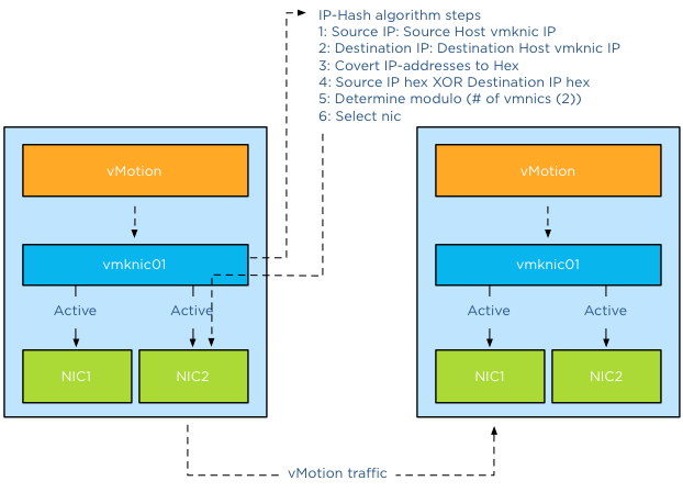
The vMotion traffic hits the load-balancing policy configured on the portgroup and the IP-Hash algorithm will select a vmnic to transmit the traffic to the destination host. Yes you read it correct, although the two links are aggregated the IP-Hash load balancing policy will always select a single NIC to send traffic. Therefor vMotion will use a single uplink (1GB in this example) to transfer vMotion traffic. With IP-hash a vMotion operation utilizes a single link, leaving the other NIC idle. Would you have used Multi-NIC vMotion, vMotion would have balanced the traffic across the multiple vmknics even for a single vMotion operation.
Utilization aware
Using the same scenario, vMotion determines that this host is allowed to have 4 concurrent vMotion operations. Unfortunately IP-Hash does not take utilization into account when selecting the NIC. The selection is done on a source-destination IP hash, decreasing the probability of load balancing across multiple NICs when using a small number of IP-addresses. This situation is often applicable to the vMotion subnet; this subnet contains a small number of IP-addresses used by the vMotion vmknics. Possibly resulting IP-HASH selecting the same NIC for the same concurrent vMotion operations. This in turn may lead to oversaturating a single uplink while leaving the other uplink idling. Would you have used Multi-NIC vMotion, vMotion would have balanced the traffic across the multiple vmknics, providing an overall utilization of both NICs.
Key takeaways
Link aggregation does not provide a big fat pipe to vMotion, due to the IP-Hash load balancing policy, a single nic will be used for a vMotion operation. IP-Hash is not utilization aware, possibly distributing traffic unevenly due to small number of source and destination IP-addresses. Multi-NIC vMotion distributes vMotion traffic across all available vmknics, for both single vMotion operations and multiple concurrent vMotion operations. Multi-NIC vMotion provides a better overall utilization of NICs allocated for the vMotion processes.
Part 1 – Designing your vMotion network
Part 2 – Multi-NIC vMotion failover order configuration
Part 3 – Multi-NIC vMotion and NetIOC
Part 5 – 3 reasons why I use a distributed switch for vMotion networks