• Skip to primary navigation
  • Skip to main content

frankdenneman.nl

  • AI/ML
  • NUMA
  • About Me
  • Privacy Policy

Search Results for: machine learning

Project Monterey and the need for Network Cycles Offload for ML Workloads.

October 6, 2021 by frankdenneman

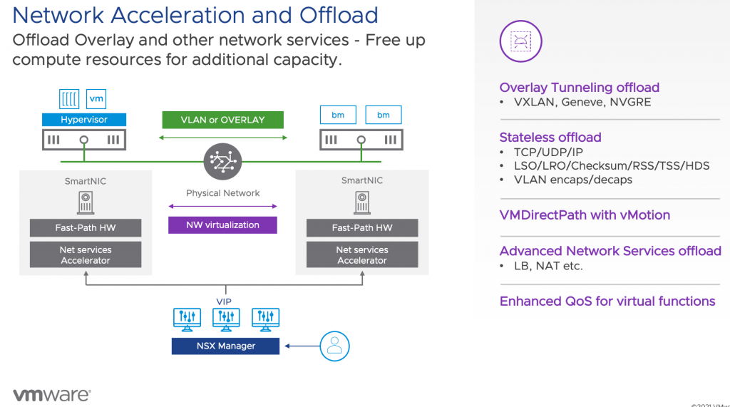
VMworld has started, and that means a lot of new announcements. One of the most significant projects VMware is working on is project Monterey. Project Monterey allows the use of SmartNICS, also known as Data Processing Units, of various VMware partners within the vSphere platform. Today we use the CPU inside the ESXi host to run workloads and to process network operations. With the shift towards distributed applications, the CPUs inside the ESXi hosts need to spend more time processing network IO instead of application operations. This extra utilization impacts data center economics like consolidation ratios and availability calculations. On top of this shift from monolith application to distributed application is the advent of machine learning supported services in the enterprise data center.

As we all know, the enterprise data center is the goldmine of data. Business units within organizations are looking at the data. If combined with machine learning, it can solve their business challenges. And so, they use the data to train machine learning models. However, data stored in databases or coming from modern systems such as sensors or video systems cannot be directly fed into the vertical application stack used for machine learning model training. This data needs to be “wrangled” into shape. The higher quality of the data, the better the model can generate a prediction or recommendation. As a result, the data flows from its source through multiple systems. Now you might say machine learning datasets are only a few 100 gigabytes in size. I’ve got databases that are a few terabytes. The problem is that a database sits nice and quietly on a datastore on an array somewhere and doesn’t go anywhere. This dataset moves from one system to another in an ML infrastructure depicted below and gets transformed, copied, and versioned many times over. You need a lot of CPU horsepower to transform the data and continuously move the data around!

One of the most frequent questions I get is why vSphere is such an excellent platform for machine learning, simply data adjacency. We run an incredible amount of database systems in the world. That holds the data of the organizations, which in turn holds the key to solve those challenges. Our platform provides the tools and capabilities to use modern technologies such as GPU accelerators and data processing units to help process the data. And data is the fuel of machine learning.

The problem is that we (the industry) haven’t gotten around to make a Tesla version of machine learning model training yet. We are in the age of gas-guzzling giants. People in the machine learning space are looking into improving techniques for datasets for model training. Instead of using copious amounts of data, use more focused data points. But that’s work in progress. In the meantime, we need to deal with this massive data stream flowing through many different systems and platforms that typically run within virtual machines and containers on top of the core platform vSphere. Instead of overwhelming the X86 CPUs in the ESXi host to deal with all the network traffic generated by sending those datasets between the individual components of the ML infrastructure, we need to offload it to another device in an intelligent way. And that’s where project Monterey can come into play.

There are many presentations about project Monterey and all it’s capabilities. I would suggest you start with “10 Things You Need to Know About Project Monterey” by Niels Hagoort #MCL1833

Filed Under: AI & ML

PCIe Device NUMA Node Locality

January 10, 2020 by frankdenneman

During this Christmas break, I wanted to learn PowerCLI properly. As I’m researching the use-cases of new hardware types and workloads in the data center, I managed to produce a script to identify the PCIe Device to NUMA Node Locality within a VMware ESXi Host. The script set contains a script for the most popular PCIe Device types for data centers that can be assigned as a passthrough device. The current script set is available on Github and contains scripts for GPUs, NICs and (Intel) FPGAs.

PCIe Devices Becoming the Primary Units of Data Processing

Due to the character of new workloads, the PCIe device is quickly moving up from “just” being a peripheral device to become the primary unit for data processing. Two great examples of this development are the rise of General Purpose GPU (GPGPU), often referred to as GPU Compute, and the virtualization of the telecommunication space.

The concept of GPU computing implies using GPUs and CPUs together. In many new workloads, the processes of an application are executed on a few CPU cores, while the GPU, with its many cores, handles the computational intensive data-processing part. Another workload, or better said, a whole industry that leans heavily on the performance of PCIe devices, is the telecommunication industry. Virtual Network Functions (VNF) require platforms using SR-IOV capable NICs or SmartNICs to provide ultra-fast packet processing performance.

In both scenarios having insight into PCIe Device to processor locality is a must to provide the best performance to the application or avoid introducing menacing noisy neighbors that can influence the performance of other workloads active in the system.

PCIe Device NUMA Node Locality

The majority of servers used in VMware virtualized environments are two CPU socket systems. Each CPU socket accommodates a processor containing several CPU cores. A processor contains multiple memory controllers offering a connection to directly connected memory. An interconnect (Intel: QuickPath Interconnect (QPI) & UltraPath Interconnect (UPI), AMD: Infinity Fabric (IF)) connects the two processors and allows the cores within each processor to access the memory connected to the other processor. When accessing memory connected directly to the processor, it is called local memory access. When accessing memory connected to the other processor, it is called remote memory access. This architecture provides Non-Uniform Memory Access (NUMA) as access latency, and bandwidth differs between local memory access or remote memory access. Henceforth these systems are referred to as NUMA systems.

It was big news when the AMD Opteron and Intel Nehalem Processor integrated the memory controller within the processor. But what about PCIe devices in such a system? Since the Sandy Bridge Architecture (2009), Intel reorganized the functions critical to the core and grouped them in the Uncore, which is a “construct” that is integrated into the processor as well. And it is this Uncore that handles the PCIe bus functions. It provides access to NVMe devices, GPUs, and NICs. Below is a schematic overview of a 28 core Intel Sky lake processor showing the PCIe ports and their own PCIe root stack.

Intel Skylake Mesh Architecture

In essence, a PCIe device is hardwired to a particular port on a processor. And that means that we can introduce another concept to NUMA locality, which is PCIe locality. Considering PCIe locality when scheduling low-latency or GPU compute workload can be beneficial not only to the performance of the application itself but also to the other workloads active on the system.

NUMA Locality Venn Diagram

For example, Machine Learning involves processing a lot of data, and this data flows within the system from the CPU and memory subsystem to the GPU to be processed. Properly written Machine Learning application routines minimize communication between the GPU and CPU once the dataset is loaded on the GPU, but getting the data onto the GPU typically turns the application into a noisy neighbor to the rest of the system. Imagine if the GPU card is connected to NUMA node 0, and the application is running on cores located in NUMA node 1. All that data has to go through the interconnect to the GPU card.

The interconnect provides more theoretical bandwidth than a single PCIe 3.0 device can operate at, ~40 GB/s vs. 15 GB/s. But we have to understand that interconnect is used for all PCIe connectivity and memory transfers by the CPU scheduler. If you want to explore this topic more, I recommend reviewing Amdahl’s Law – Validity of the single processor approach to achieving large scale computing capabilities – published in 1967. (Still very relevant) And the strongly related Little’s Law. Keeping the application processes and data-processing software components on the same NUMA node keeps the workloads from flooding the QPI/UPI/ AMD IF interconnect.

For VNF workloads, it is essential to avoid any latency introduced by the system. Concepts like VT-d (Virtualization Technology for Directed I/O) reduces the time spent in a system for IOs and isolate the path so that no other workload can affect its operation. Ensuring the vCPU operates within the same NUMA domain ensures that no additional penalties are introduced by traffic on the interconnect and ensures the shortest path is provided from the CPU to the PCIe device.

Constraining CPU Placement

The PCIe Device NUMA Node Locality script assists in obtaining the best possible performance by identifying the PCIe locality of GPU, NIC of FPGA PCIe devices within VMware ESXi hosts. Typically VMs running NFV or GPGPU workloads are configured with a PCI passthrough enabled device. As a result, these VMware PowerCLI scripts inform the user which VMs are attached directly to the particular PCIe devices.

Currently, the VMkernel schedulers do no provide any automatic placement based on PCIe locality. CPU placement can be controlled by associating the listed virtual machines with a specific NUMA node using an advanced setting.

Please note that applying this setting can interfere with the ability of the ESXi NUMA scheduler to rebalance virtual machines across NUMA nodes for fairness. Specify NUMA node affinity only after you consider the rebalancing issues.

The Script Set

The purpose of these scripts is to identify the PCIe Device to NUMA Node locality within a VMware ESXi Host. The script set contains a script for the most popular PCIe Device types for Datacenters that can be assigned as a passthrough device. The current script set contains scripts for GPUs, NICs, and (Intel) FPGAs.

Please note that these scripts only collect information and do not alter any configuration in any way possible.

Requirements

  • VMware PowerCLI
  • Connection to VMware vCenter
  • Unrestricted Script Execution Policy
  • Posh-SSH
  • Root Access to ESXi hosts

Please note that Posh-SSH only works on Windows version of PowerShell.

The VMware PowerCLI script primarily interfaces with the virtual infrastructure via a connection to the VMware vCenter Server. A connection (Connect-VIServer) with the proper level of certificates must be in place before executing these scripts. The script does not initiate any connect session itself. It assumes this is already in-place.

As the script extracts information from the VMkernel Sys Info Shell (VSI Shell) the script uses Posh-SSH to log into ESXi host of choice and extracts the data from the VSI Shell for further processing. The Posh-SSH module needs to be installed before running the PCIe-NUMA-Locality scripts, the script does not install Posh-SSH itself. This module can be installed by running the following command Install-Module -Name Posh-SSH (Admin rights required). More information can be found at https://github.com/darkoperator/Posh-SSH

Root access is required to execute a vanish command via the SSH session. It might be possible to use SUDO, but this has functionality has not been included in the script (yet). The script uses Posh-SSH keyboard-interactive authentication method and presents a screen that allows you to enter your root credentials securely.

Script Content

Each script consists of three stages, Host selection & logon, data collection, and data modeling. The script uses the module Posh-SSH to create an SSH connection and runs a vsish command directly on the node itself. Due to this behavior, the script creates an output per server and cannot invoke at the cluster level.

Host Selection & Logon

The script requires you to enter the FQDN of the ESXi Host, and since you are already providing input via the keyboard, the script initiates the SSH session to the host, requiring you to login with the root user account of the host. When using the GPU script, the input of the GPU vendor name is requested. The input can be, for example, NVIDIA, AMD, Intel, or any other vendor providing supported GPU devices. This input is not case-sensitive.

Data Collection

The script initiates an esxcli command that collects the PCIe address of the chosen PCIe device type. It stores the PCIe addresses in a simple array.

Data Modeling

The NUMA node information of the PCIe device is available in the VSI Shell. However, it is listed under the decimal value of the Bus ID of the PCIe address of the device. The part that follows is a collection of instructions converting the full address space into a double-digit decimal value. Once this address is available, it’s inserted in a VSISH command and execute on the ESXi host via the already opened SSH connection. The NUMA node, plus some other information, is returned by the host, and this data is trimmed to get the core value and store it in a PSobject. Throughout all the steps of the data modeling phase, each output of the used filter functions is stored in a PSObject. This object can be retrieved to verify if the translation process was executed correctly. Call $bdfOutput to retrieve the most recent conversion. (as the data of each GPU flows serially through the function pipeline, only the last device conversion can be retrieved by calling $bdfOutput.

The next step is to identify if any virtual machines registered on the selected host are configured with PCIe passthrough devices corresponding with the discovered PCIe addresses.

Output

A selection of data points is generated as output by the script:

PCIe
Device
Output Values
GPUPCI ID, NUMA Node, Passthrough Attached VMs
NICVMNIC name, PCI ID, NUMA Node, Passthrough Attached VMs
FPGAPCI ID, NUMA Node, Passthrough Attached VMs

The reason why the PCI ID address is displayed is that when you create a VM, the vCenter UI displays the (unique) PCI-ID first to identify the correct card. An FPGA and GPU do not have a VMkernel label, such as the VMNIC label of a network card. No additional information about the VMs is provided, such as CPU scheduling locations or vNUMA topology, as these are expensive calls to make and can change every CPU Quorum (50 ms).

It’s recommended to review the CPU topology of the virtual machine and if possible to set the NUMA Node affinity following the instructions listed in VMware Resource Management Guide. Please note that using this advanced setting can impact the ability of the CPU and NUMA schedulers to achieve an optimal balance.

Using the Script Set

  • Step 1. Download the script by clicking the “Download” button on the Github repository
  • Step 2. Unlock scripts (Properties .ps1 file, General tab, select Unlock.)
  • Step 3. Open PowerCLI session.
  • Step 4. Connect to VIServer
  • Step 5. Execute script for example, the GPU script: .\PCIE-NUMA-Locality-GPU.ps1
  • Step 6. Enter ESXi Host Name
  • Step 7. Enter GPU Vendor Name
  • Step 8. Enter Root credentials to establish SSH session

Step 8. Consume output and possibly set NUMA Node affinity for VMs

Acknowledgments

This script set would not have been created without the guidance of @kmruddy and @lucdekens. Thanks, Valentin Bondzio, for verification of NUMA details and Niels Hagoort and the vSphere TM team for making their lab available to me.

Filed Under: NUMA, VMware

Basic Terminologies Large Language Models

August 18, 2023 by frankdenneman

Many organizations are in the process of deploying large language models to apply to their use cases. Publically available Large Language Models (LLMs), such as ChatGPT, are trained on publicly available data through September 2021. However, they are unaware of proprietary private data. Such information is critical to the majority of enterprise processes. To help an LLM to become a useful tool in the enterprise space, an LLM is further trained of finetuned on proprietary data to adapt to organization-specific concepts.

This process introduces terminology that is used more often outside the data science community. Having a better understanding of the following concepts should enhance your ability to navigate the data science team’s requirements when building an LLM deployment architecture.

Neural Network: A Large Language Model (LLM) is a sophisticated neural network architecture designed for natural language processing tasks. LLMs use multiple layers of interconnected nodes to learn language patterns from vast amounts of text data. Parameters, specifically weights, and biases, are crucial components that define how the model processes information.

Weights govern the strength of connections between nodes, influencing the LLM’s ability to capture linguistic nuances. Biases adjust the activation levels of nodes, allowing the model to adapt its responses. During forward propagation, the input text is transformed into tokens and flows through the network, undergoing contextual analysis and predicting subsequent words or phrases.

Backward propagation, an integral part of training, calculates gradients to adjust weights and biases. This process refines the model’s parameters, aligning its language generation with human-written text. Through continuous learning, LLMs become adept at tasks like completing text, translating, and generating new content.

Large Language Model: A Large Language Model is a specific Natural Language Processing (NLP) model that predicts the next word or token. Compared to other NLP models (which are based on language models LM), they are characterized by their size (parameter count of >1B) and are typically trained on vast amounts of text data from the internet. This enables them to learn a broad range of language features and general knowledge. LLMs can handle a number of tasks, from summarization to content generation to question and answer. NLP models are typically focused on sentiment analysis and text classification. LLMs can be further fine-tuned for various tasks with minimal additional training, while NLP is less versatile and requires extensive task-specific training. 

Foundation model: A foundation model is an LLM, sometimes referred to as a Pretrained Language Model (PLM), that is robust enough to act as a “foundation” that can be used as is or fine-tuned/adapted for newer domains. In general, it is trained on diverse data, capable of being customized and fine-tuned for various applications and tasks. For example, the open-source LLaMA 2 models are trained on 2 trillion tokens primarily sourced from publicly available online data sources. Meta required 368640 GPU (A100-80 GBs) hours to train the 13B LLaMa-2 model.  

Token: A token is a fundamental unit of text that an LLM uses to process and understand language. In English, a token can be as short as a single character or as long as a word. For example, in the sentence “I love vSphere,” there are three tokens: “I,” “love,” and “vSphere.” However, the word “vSphere” might be broken down into two tokens depending on the model’s tokenizer. Token length is important because it can impact the overall size of the input data, computational resources required for processing, and the model’s ability to perform linguistically. Tokens help break down the text into manageable pieces for analysis and are essential for language generation. They serve as the building blocks that allow LLMs to comprehend human language. 

Embeddings: are numerical representations of tokens. Each token is transformed into a vector of numbers. These vectors encode the semantic meaning of the text and facilitate computer-based processing and analysis of human language. This language-to-number translation equips machine-learning processes to interact with language data efficiently.

Vector: Vectors are commonly used to represent data points in a multi-dimensional space. Each element of a vector corresponds to a specific dimension, and the combination of these elements defines the position of the vector in that space. Vectors are essential for measuring similarities and transforming data. The article “Explaining Vector Databases in 3 Levels of Difficulty” provides a great primer on vectors, embeddings, and Vector databases.

Image by Leonie Monigatti

Parameters: Parameters are the learned values that a model acquires through training to facilitate predictions or classifications on new data. In neural networks, these parameters are commonly denoted as weights and biases, dictating how input data undergoes transformation into output predictions.    

An LLM model size is typically expressed in parameter count in billions, such as the LLaMA-2 13B. This model contains roughly 13 Billion parameters. The memory consumption depends on the floating-point format (precision). Typically for LLM, a BF16 or FP16 is used. A parameter using BF16 consumes 2 bytes. 1 Billion bytes equal a gigabyte. Thus, we can easily calculate the “static” model memory consumption. LLaMA-2 13B consumes 26 GB of GPU memory when loaded into the GPU. Streaming data into the LLM or fine-tuning the model increases memory consumption. 

Transformer Architecture: The transformer architecture is a foundational framework for training and utilizing large neural networks in natural language processing (NLP). It revolutionized the field by introducing the attention mechanism, which allows the model to weigh the importance of different words in a sentence. It introduced a self-attention mechanism to process input data in parallel, allowing it to truly understand the context of words depending on other words that are placed further away within the sentence (long-range dependencies). The transformer architecture has an encoder and decoder functionality. The encoder creates a “contextualized representation” of a prompt, capturing the meaning and significance of the words in the prompt by considering how they relate to each other within the given context. The decoder receives and processes the contextualized representation, using its understanding of the context to guide output generation. Typically, it generates one word of the output at a time. The first word generated is based on the input context, and the next word is generated based on the input context and the previously generated word. This is called autoregressive context.

(Downstream) Task: An LLM is typically refined further to achieve a specific goal or perform a particular downstream task. Many foundation models today can perform a wide range of NLP tasks without refinement for a particular downstream task. A “task” refers to a specific job or activity that the model is designed to perform using its language understanding and generation capabilities. Tasks can include a wide range of natural language processing objectives. The most common ones are text generation (predicting the next word/token), summarization (given an input, return a short output), question answering (predicting the next word/token based on search results in the prompt), sentiment analysis, translation, and instruction. When a new downstream task is needed, we still need to fine-tune the foundation LLM to respond to domain-specific prompts (eg; ensure it favors a particular term, “Tanzu,” over others).  

Prompt: A prompt is a specific input given to the model to guide its behavior and generate desired text output. The prompt serves as an instruction or query that helps the LLM understand the task or context it needs to respond to. It can be a sentence, a paragraph, or even just a few keywords, depending on the task at hand. For example, if technical marketing wants an LLM to generate a technical specification overview, they can use the prompt “Write a detailed description of our latest update release, highlighting its unique features and capabilities.”

Prompt engineering: The quality and specificity of the prompt can greatly influence the LLM’s output. A well-crafted prompt provides clear guidance to the model, leading to more relevant and accurate generated text. Prompt engineering involves designing prompts effectively to achieve the desired results for various tasks such as translation, summarization, question answering, and more. Prompt engineering can also be used to induce LLMs to say undesirable things, for example, with a prompt that tells an LLM to forget its existing rules before responding. 

Zero-shot: refers to the model’s ability to perform tasks or generate text about new topics without additional training or examples in the prompt. It relies on its existing knowledge to tackle new challenges without requiring specific learning for each one. 

P-tuning: This technique involves fine-tuning a small trainable model prior to engaging the LLM. The small model encodes the text prompt and crafts task-specific virtual tokens, which are then added to the prompt and fed into the LLM. Once the fine-tuning is done, these virtual tokens are stored in a lookup table and used during inference, replacing the smaller model. P-tuning is far more resource efficient compared to other forms of fine-tuning of an LLM. The time required to tune a smaller model can often be measured in minutes instead of days with fine-tuning the LLM.   This is a great talk about P-tuning and what exactly virtual tokens are.

Parameter Efficient Fine-Tuning: PEFT aims to make the fine-tuning process more efficient by focusing on updating only a subset of the model’s parameters (e.g., 100M parameters for a 15B model), rather than retraining the entire model from the ground up. The idea behind PEFT is to balance retaining the knowledge captured by the pre-trained model and tailoring it to perform well on a specific task. By carefully selecting and adjusting certain parameters, you can achieve good performance on the task while reducing the computational cost and time required for fine-tuning. PEFT also overcomes the issues of catastrophic forgetting, a behavior observed during the full fine-tuning of LLMs. There are multiple PEFT methods: : 

Adapter-based PEFT: Adapters are new modules added to the pre-trained network, and only the new parameters are trained, while the original LLM-trained parameters are left untouched. As a result, a small proportion of parameters of the original LLM is trained. This means that the model keeps remembering the previous tasks and uses a small number of new parameters to learn the new task. However, the downside of adding these new layers is the inference latency increase. This issue appears unavoidable because the adapter layers are added sequentially to an LLM. They must be processed sequentially, and there is no way to parallel process them.   

LoRA: Low-Rank Adaptation of Large Language Models: LoRA also freezes the pre-trained parameters, but instead of adding additional layers to the neural network, it adds values to the parameters. As a result, the model can be executed fully in parallel, avoiding additional inferencing latency. In addition, LoRA applies a very intelligent method to reduce the number of trainable parameters, reducing fine-tuning time and memory consumption. A further reduction of memory consumption can be achieved by quantizing the majority (non-outliers) trainable parameters, which results in using an integer data type (INT8) instead of a floating point. A parameter stored in INT8 consumes 8 bits, reducing the memory footprint in half compared to BF16. This is the most popular method of PEFT.  

Quantized Low-Ranking Adaptation (QLoRA):  QLoRA takes it one step further and compresses the weights and activations to 4-bit precision. QLoRA uses a specific data type for storing the base model weights and data type to perform computations. During the computations, QLoRA “dequantizes” the weights from a 4-bit precision (4-bit NormalFloat) into a 16-bit bfloat. The weights are only decompressed when needed; therefore, QLoRA allows large models to run on GPUs with smaller memory capacities.   

IA3 (Infused Adapter by Inhibiting and Amplifying Inner Activations): IA3 is a newer PEFT technique intended to improve over LoRA. It offers the same benefits as the LoRA. However, it’s only tested on really “small” LLM models (3B) currently, and most backends do not support this yet. The last update on the GitHub IA3 repo was done in September 2022, which might hint at a lack of popularity of this PEFT method in the data science community. 

Fine Tuning: Fine-tuning is the mechanism to improve LLM models for a specific task (e.g., summarizing legal documents) or domain (e.g., more knowledge about virtualization). During the training of an LLM, the neural network is exposed to unlabeled data and learns through a form of self-supervision (e.g., predicting the next word or sentence entailment). That means that the algorithm explores the patterns, structures, and relationships within the dataset on its own without being provided with specific labeled output for every task, but the robustness of its dataset may mean that it will already be good at some tasks (eg; generating coherent sounding sentences). Fine-tuning always involves supervised learning, where human labelers validate and curate data for a specific task (e.g., to fine-tune the model’s question-answering capabilities, we would have question and answer pairs as the input).  

Reinforcement Learning with Human Feedback (RLHF): When validating the accuracy of a model designed for an image recognition task, we can quickly determine its accuracy. It either classifies the cat correctly or not. With LLMs, it’s a bit more challenging, as it is more difficult to define what makes a “good” text as it is subjective and context-dependent.    

The RHLF method uses feedback generated by humans for generated text to measure the model performance. The method involves deploying multiple models during the training process. A pretrained language model and typically a smaller reward model. The PLM generates multiple responses based on a prompt and a reward model numerical scores each response on how well humans perceive this text. It ranks the response according to human preference and then applies reinforcement learning to train the PLM further to prioritize the response with the higher numerical scores.  

RHLF systems are complex and challenging as gathering human preference data is expensive. RLHF performance is only as good as the quality of the human annotations. People tend to disagree. Therefore, ground truth is often lacking due to variance in opinions by the annotating team.  There are multiple methods of human feedback besides the preference order, such as: 

  • Corrections: Upvoting or downvoting the model output (also known as prompt completion) 
  • Demonstrations: Humans write the preferred answer to a prompt 
  • Natural Language Input: Humans are asked to provide feedback on the model output in natural language 

Supervised fine-tuning (SFT): involves adapting a PLM to a specific downstream task using validated training examples. Validated training examples are pairs of input data and output labels that have been carefully checked and confirmed to be accurate and reliable. SFT tunes the model to a specific task, such as responding to customer support questions. The model can be trained to adapt to specific knowledge-based or demonstrate a particular persona or empathy by using validated training examples.  

Is PEFT considered supervised learning?:  PEFT is not strictly categorized as supervised learning; rather, it is a technique that can be applied within the context of supervised learning. Supervised learning involves training a model on labeled data pairs, where the labels serve as the ground truth for training. PEFT, on the other hand, is a method that aims to fine-tune a pre-trained model using a limited amount of new data specific to a task to adapt the model’s parameters while leveraging its existing knowledge. PEFT is characterized by its emphasis on efficiency and parameter reuse. It does not require extensive retraining on the entire dataset, as it focuses on updating only a subset of the model’s parameters to adapt it to a new task.

In-Context Learning 

Retrieval Augmented Generation (RAG): Once an LLM is trained, it is ignorant of new data. When an organization launches a new product or service, the customer service-focused LLM needs to be retrained to incorporate these new data points. RAG allows the LLM to act as a conversational interface, while RAG “grounds” the LLM with information that aligns with its use case while reducing hallucinations. RAG allows LLMs to access knowledge sources outside the trained model and augment the completion of the prompt with relevant information found in external sources. These sources can be the organizations’ proprietary data sources, like knowledge bases, Bugzilla, Confluence, internal documents, etc. RAG typically works together with a Vector Database or a search engine. 

When the user provides the prompt to the LLM, the RAG framework performs a “contextual search” on the Vector database and generates the context. The RAG framework augments the original prompt by injecting the context into the prompt. The LLM receives the enriched prompt and can generate a better response as it has access to factual data. The LLM sends the generated response back to the user.  

RAG frameworks and Vector DBs can be critical differentiators for organizations with rapidly changing knowledge bases or any other source of information. These organizations cannot change the LLM and redeploy at the same velocity as the demand for up-to-date information. Keeping the models’ answers in lock-step with the velocity of their service offering is challenging. A good example is a FAQ for a chatbot function at a call center for a new product or service. The data science team can add up-to-date data to the Vector DB answer and question domains and ensure that the RAG framework prioritizes the Vector DB over the LLM model for information retrieval. 

Grounding: refers to the process of connecting the model’s prompt completion (responses) to real-world knowledge. Grounding is about ensuring that the model’s outputs are coherent, accurate, and relevant to the information available in the world. Pretraining, prompt-engineering, fine-tuning, and in-context learning all help to ground the LLM.  

Hallucination: a hallucination is a confident response by the LLM that appears coherent and contextually relevant but is not based on accurate information from the input data or is not logically grounded in reality. An example is URLs that are generated by an LLM that does not exist.  

Guardrails: Guardrails restrict LLMs to respond in a particular (safe) manner. These guardrails guide the LLM to stay on topic, avoid hallucinations or toxic responses, or execute malicious code. Chatbots can become an attack surface, and a security guardrail can protect LLM platforms. Guardrails are programmable constraints and are placed between the chatbot and the LLM. The NVIDIA NeMo framework offers a guardrail workflow to apply constraints to the LLM easily. 

Filed Under: AI & ML

Sub-NUMA Clustering

September 21, 2022 by frankdenneman

I’m noticing a trend that more ESXi hosts have Sub-NUMA Clustering enabled. Typically this setting is used in the High-Performance Computing space or Telco world, where they need to reduce every last millisecond of latency and squeeze out every bit of bandwidth the system can offer. Such workloads are mostly highly tuned and operate in a controlled environment, whereas an ESXi server generally runs a collection of every type of workload in the organization imaginable. Let’s explore what Sub-NUMA clustering does and see whether it makes sense if you should enable it in your environment.

NUMA

Most data center server systems are NUMA systems. In a NUMA system, each CPU contains its own memory controllers that provide access to locally connected memory. The overwhelming majority of systems in data centers worldwide are dual-socket systems. Each CPU has access to local memory capacity via its own memory controller, but it can also access the memory connected and controlled by the remote CPU. There is a difference in latency and bandwidth between reading and writing local and remote memory, hence the term Non-Uniform Memory Access (NUMA). 

AMD EPYC architecture is a Multi-Chip-Module (MCM) architecture and wildly differs from the monolithic architecture and its I/O path behavior. Sub-NUMA clustering is the functionality of partitioning Intel CPU packages. AMD provides similar functionality called NUMA per Socket (NPS). This article only focuses on Intel Sub-NUMA clustering technology as I have not seen server vendors’ default enablement of the NPS setting at this moment. 

Logical Partitions

The Intel E5-2600 processor family had a ring architecture, allowing Intel to optimize CPU core-to-memory access further. With the Haswell release (v3), Intel introduced Cluster-On-Die (COD) functionality. COD logically splits the CPU into two NUMA nodes. 

The COD feature reduces the search domain of the memory hierarchy. NUMA systems are cache-coherent. When a core generates a memory request, it checks its local L1 and L2 cache, the shared L3 cache (LLC), and the remote CPU cache. By splitting the CPU along its “natural” ring structure barrier, you end up with a smaller memory domain to search if there is a cache miss. And on top of that, you should have less local memory traffic if the applications and operating systems are NUMA optimized. Please look at the NUMA deep dive or read this research paper about COD caching structures for more info. The Skylake architecture (Intel Xeon Scalable Processors) moved away from the ring architecture and introduced a mesh architecture. The logical partition functionality remained and was introduced under a new name, Sub-NUMA Clustering (SNC). 

With SNC enabled, that previously shown dual CPU socket ESXi host system is now a four NUMA node system.

Comparing SNC to NUMA Performance 

Is SNC that Turbo feature that is hidden in your BIOS? If you look at the description some vendors use, you want to enable it immediately. Dell and Lenovo describe SNC: “…It improves average latency to the LLC”. I’m using the performance numbers that Hadar Greinsmark published in his research “Effective Task Scheduling of In-Memory Databases on a Sub-NUMA Processor Topology.” In a default NUMA configuration (SNC disabled), let’s look at the latency difference between Socket 0 (S0) and Socket 1 (S1).

Latency (ns)NUMA Node 0 (S0)NUMA Node 1 (S1)
NUMA Node 080.8138.9
NUMA Node 1139.779.9

With SNC enabled, Socket 0 contains two NUMA nodes, 0 and 1. Socket 1 contains NUMA Nodes 2 and 3. These logical partitions are genuine NUMA nodes. Although the different memory controllers and cache domains are on the same die, the caching mechanisms and non-interleaving of memory controllers create a non-uniform memory access pattern between the domains. Consequently, there is an increase in latency when fetching memory from the other “remote” NUMA node located within the same socket.

Latency (ns)NUMA Node 0 (S0)NUMA Node 1 (S0)NUMA Node 2 (S1)NUMA Node 3 (S1)
NUMA Node 0 (S0)74.2 (-7.5%)81.5 (+0.8%)132.0 (-5%)142.1 (+2.3%)
NUMA Node 1 (S0)82.0 (+1.4%)76.4 (-5.4%)135.6 (-2.4%)144.5 (+4%)
NUMA Node 2 (S1)132.4 (-5.2%)142.0 (+1.7%)73.6 (-7.9%)81.5 (+2%)
NUMA Node 3 (S1)136.0 (-2.6%)144.4 (+3.4%)81.5 (+2%)76.6 (-4.1%)

The SNC mapping method of memory addresses from the local memory controller to the closest LLC certainly works as the local NUMA latency with SNC drops on average between 6 to 7% compared to the default NUMA configuration. Take NUMA node 0 as an example. With SNC enabled, it experiences a memory latency of 74.2 ns; compared to SNC disabled, the access latency is 80.8 ns. As a result, SNC specifically reduces memory latency by 7.5% for NUMA node 0. 

The performance numbers show that remote connections handled by node 0 and node 2 are performing better than in the SNC disabled state, whereas NUMA node 1 and node 3 are performing less than in the SNC disabled state. The latency numbers reported to the remote node on the same socket are very interesting. It possibly shows the fascinating behavior of the interconnect architecture. However, Intel does not share detailed information about the Ultra Path Interconnect (UPI) framework. 

If we look at the architecture diagram, we notice that above NUMA node 0, a controller exists with two UPI connections. Above NUMA node 1, a controller is located with a single UPI connection. Possibly the single-UPI experiences more blocking I/O traffic on the mesh, whereas the UPI controller with two connections has more methods to manage the flow better.

But this is just pure speculation on my end. The latency shoots up if we look at the absolute remote I/O numbers. What matters is that workloads execute remote I/O operations if they cannot read or write memory locally. If it can find the memory in the NUMA node located on the same socket, it sees a latency increase of 8.6%. When it travels across the interconnect to a NUMA node in the other socket, the latency increases to 78.2%. When it needs to travel to the farthest NUMA node, latency almost doubles (90%). A default NUMA system has an average remote latency hit of 73%. But SNC has a more extensive performance spread as it improves up to 7% on average locally but also degrades remote memory access up to 5%. Let’s compare. In the default situation, local access is 80 ns, and remote access is 138.9 ns. With SNC, it has to deal with a worst-case scenario of 73.6 ns vs. 142.0. Which is the reason why the performance gap extends to 92.9%. And what decides what workload becomes local and remote? That is the key of this article. But before we dive into that, let’s look at bandwidth performance first. 

Bandwidth

Your Skylake CPU model has either two or three UPI links. Each UPI link is a point-to-point full duplex connection with separate lanes for each direction. A UPI link has a theoretical transfer speed of 10.4 Gigatransfers per second (GT/s), which translates to 20.8 gigabytes per second (GB/s). The Intel Xeon Platinum 8180 processor used in the report contains three UPI links, possibly providing an aggregated theoretical bandwidth of 62.4 GB/s. One controller has two UPI links, and the other controller has one UPI link. The research paper shows that when communicating with a remote node, the average bandwidth is roughly 34.4 GB/s. 

Speculation 

As limited information about UPI communication patterns is available, I assume the system uses only two UPI links in the default NUMA node. With default NUMA, memory interleaves across memory controllers; thus, memory has to be retrieved from both memory controllers, and therefore, the systems use both UPI controllers. Why it doesn’t use all three links, I think the overhead of syncing the I/O operation across three links and allowing other operations to use the interconnect outweighs the potential benefit of additional uplink. 

/speculation

But let’s stick to the facts. Here you see the impact of remote memory access. Bandwidth performance drops 69% when doing remote I/O on the default NUMA system. And for this exact reason, you want to have NUMA optimized workloads or right-sized virtual machines. Why doesn’t the progress bar move linearly on your screen? Possibly some non-NUMA optimized code fetching memory from the remote NUMA node. 

Bandwidth (MB/s)NUMA Node 0 (S0)NUMA Node 1 (S1)
NUMA Node 0111 08334 451
NUMA Node 134 455111 619

With SNC enabled, the system stops interleaving the whole memory range across both memory controllers within the CPU package and assigns each memory controller a subset of the memory range. Each memory controller has three channels, splitting the NUMA node’s bandwidth in half. The test system uses DDR4 2666 MHz (21.3 GB/s) memory modules, theoretically providing up to 63.9 GB/s per SNC NUMA node. When reviewing the research findings, the default NUMA node provided 111 GB/s (6 channels) by enabling SNC, which should result in approximately 55.5 GB/s per NUMA node. Yet the test results report 58 GB/s. SNC improves local bandwidth by an average of 4.5% due to the isolation of workload and, therefore, fewer blocking moments of other I/O operations on the mesh. Similar improvements occur for the NUMA node on the same socket.

Bandwidth (MB/s)NUMA Node 0 (S0)NUMA Node 1 (S0)NUMA Node 2 (S1)NUMA Node 3 (S1)
NUMA Node 0 (S0)58 08758 12334 25434 239
NUMA Node 1 (S0)58 14558 01334 26634 235
NUMA Node 2 (S1)34 28834 24858 06458 147
NUMA Node 3 (S1)34 28834 25458 14558 007

Therefore, SNC is a great way to squeeze out that last bit of performance for a highly tuned workload. If the workload fits inside the smaller NUMA node from a core count and memory capacity, it can expect a 7% improvement in latency and a 4% memory bandwidth. But, and there is a big but, but not the way Sir Mix-a-Lot likes it. But only if you deploy a scale-out workload. If you can deploy two workers in each worker node that run separate workloads, they both can benefit from extra obtainable bandwidth. If you only deploy a single workload, you’ve just robbed that workload of half its obtainable bandwidth. The workload can access remote memory capacity and possibly obtain more bandwidth. Still, it’s up to the NUMA scheduler or application’s discretion to make the smart move and choose the right NUMA node. And this is the point where we arrive at the fork in the road, the difference between a dedicated workload on bare metal and dealing with a NUMA scheduler that must take entitlement and workload patterns into account of multiple workloads.

SNC effectively reduces the per-NUMA node capacity and, thus, decreases the boundary of the single NUMA node virtual machine size. I have a question: Do 4% bandwidth improvement for scale-out the workload and 7% latency improvement sound like something you want to enable on a virtualization platform? How is a 10-vCPU VM placed on a dual socket with 18 cores per CPU package system?

Single NUMA node VM sizing

Not every application is NUMA aware. Most platform operators and admin teams attempt to “right-size” the virtual machine to circumvent this problem. Right-sizing means the VM contains fewer vCPUs and memory capacity than the CPU socket contains CPU cores and memory capacity, yet still can function correctly. With SNC, the NUMA node is split in half, resulting in smaller VMs if they need to fit inside a single NUMA node. 

vNUMA Topology

If a VM contains more vCPUs than a NUMA node contains CPU cores, the NUMA scheduler in ESXi creates a vNUMA topology for this VM and exposes this to the guest OS for NUMA optimizations. The NUMA scheduler creates multiple NUMA clients for this VM and places these accordingly, which is the key to understanding why SNC should or shouldn’t be enabled in your environment.

Initial placement

The NUMA scheduler gets an initial placement request if a VM is powered on or a virtual machine is migrated into the host via DRS. During the initial placement operation, the NUMA scheduler is aware of the distance between the NUMA nodes. And it will attempt to optimize the placement of the NUMA clients of the VMs. In other words, it attempts to place the NUMA clients as close to each other as possible. As a result, most of the time, if a VM consists of two NUMA clients, both NUMA clients are placed on NUMA nodes sharing the same socket with SNC enabled. 

Typically this happens during every synthetic test where this VM is the only VM running on the host; thus, the NUMA scheduler does not have to deal with contention or a complex puzzle or to fit these new clients amongst the other busy 44 other NUMA clients. 

NUMA load-balancing

The hypervisor is a very dynamic environment. The CPU scheduler has to deal with a variety of workload patterns, and there are workload patterns such as load correlation and load synchronicity. With load correlation, the schedulers must deal with the load spikes generated by the relationship between workloads running on different machines. The NUMA scheduler reviews the CPU load every 2 seconds to catch these patterns. For example, an application with a front-end VM communicates with a database. With load synchronicity workloads trend together, a VDI environment that spins up several desktops each morning will cause a persistent load spike. And so, the NUMA load-balancer might decide that it’s better to move some NUMA clients around the system. Getting into the NUMA load balancing algorithm’s details is too deep for this article. I’ve covered most in the NUMA deep dive. But the crucial thing to understand is that if it’s necessary to move the NUMA client, it will move the NUMA client, but it won’t take distance into account. The attempt will be the smartest thing to do for the system, but it might not always be the best for the VM. 

In many cases, If you would not enable SNC, that VM would have fit inside a single NUMA node, and no remote access occurred as it would fit a single NUMA node. With SNC, a large VM might be larger than the SNC-NUMA node size and thus is split up. It’s even worse if this VM connects to a PCIe device such as a GPU. Batch data transfers can occur across the interconnect, creating inconsistent data loading behavior during the host-to-device memory transfer operations. Learn more about NUMA PCI-e locality here.

SNC Enabled by Default

Why am I making this statement? I discovered that HP enabled SNC with the workload profiles “Virtualization – Max Performance” and “General Throughput Compute.”

ESXi does not have a setting in the UI that shows whether SNC is enabled or not, but we can apply the beautiful art form of deduction. By running the following (unsupported) command via SSH on the ESXi host:

echo "CPU Packages";vsish -e dir /hardware/cpu/packageList;echo "NUMA nodes";vsish -e dir /hardware/cpuTopology/numa/nodes

You get a list of the number of CPU packages (a fancy name for the device you can hold in your hand that contains the CPU cores, memory controllers, and PCI controllers) and the number of NUMA nodes in the system. If SNC is disabled, the number of NUMA nodes should equal the number of CPU packages. In this scenario, SNC is enabled. In most systems, you can enable and disable the setting individually, but if it’s part of a profile such as on the HP systems, you need to customize this. Dan tweeted the method to do this. 

Wrong on the HPE Side:https://t.co/XINRaD716y
"General Power Efficient Compute" is the default.
SNC = Disabled

I see SNC = Enabled on "Virtualization – Max Performance"
To change this but keep all other profile settings, set to Virt Max, Save, then Custom, then disable SNC.

— 🏴‍☠️ Dan (@Casper042) September 8, 2022

Disclaimer!

Please note that this tweet and this article are not official VMware recommendations to turn off SNC. This article will help you understand the implication of SNC on the overall behavior of SNC on the hardware layer and the way ESXi NUMA scheduler works. Always test a setting in your environment and your workload in a normal operating condition before changing a production environment.

My Personal Thoughts on SNC

I believe that SNC has very little to offer to a virtualization platform that runs all types of workloads. Workloads that range from tiny to monster VMs. If you have a dedicated vSphere platform running a specific low-latency workload that needs to run, for example, VOIP workload or High-Frequency Trading workload, then SNC makes sense. 

For the average vSphere environment that runs Oracle, SQL, or any high-performing database that needs lots of vCPUs, along with some front-end applications and a whole bunch of other frameworks, SNC will impact your performance. Most admins want the VM to fit inside a single NUMA node. SNC reduces the VM footprint. SNC taxes memory access more severely. Due to the increased gap between local and remote I/O, the user will detect an even more inconsistent feel of workload performance. The NUMA scheduler now needs to balance four smaller NUMA domains instead of two larger ones; thus, more decisions will be made that might not be optimal. Take Short-Term Migration, for example. The NUMA scheduler moves a VM to solve an imbalance between NUMA nodes. In that scenario, the scheduler migrates the vCPU immediately, but the memory follows more slowly. Since memory relocation is not immediate, remote memory access will temporarily increase while the pages migrate to the new NUMA node. With four smaller NUMA nodes to deal with, this can impact the overall user experience, especially if the gap between local and remote memory is enlarged from 69% to 90%.

VMs that could be Uniform Memory Access VM (fit inside a single NUMA node) now span multiple NUMA nodes. And as a result, we hope the guest OS and the application are NUMA optimized. Recent Linux optimization to their NUMA scheduler makes me hopeful, but keeping the host to default NUMA would avoid so many performance inconsistencies. 

In essence, It is my opinion that SNC is for the highly optimized, well-curated environment that has exploited every single trick in the book. It should not be the starting point for every virtualization platform. 

Want to learn more about NUMA? We spoke with the driving force behind NUMA optimizations at VMware in episode 19 of the Unexplored Territory Podcast. You can listen to the conversation with Richard Lu via the Unexplored Territory website, Apple Podcasts or Spotify

Filed Under: NUMA

Solving vNUMA Topology Mismatch When Migrating between Dual Socket Servers and Quad Socket Servers

March 11, 2022 by frankdenneman

I recently received a few questions from customers migrating between clusters with different CPU socket footprints. The challenge is not necessarily migrating live workloads between clusters because we have Enhanced vMotion Compatibility (EVC) to solve this problem. 

For VMware users just learning about this technology, EVC masks certain unique features of newer CPU generations and creates a generic baseline of CPU features throughout the cluster. If workloads move between two clusters, vMotion still checks whether the same CPU features are presented to the virtual machine. If you are planning to move workloads, ensure the EVC modes of the clusters are matching to get the smoothest experience.

The challenge when moving live workloads between ESXi hosts with different socket configurations is that vNUMA topology of the virtual machine does not match the physical topology. A virtual NUMA topology exists out of two components, the component that presents the CPU topology to the virtual machine, called the VPD. The VPD exists to help the guest OS and the applications optimize their CPU scheduling decisions. This VPD construct is principally the virtual NUMA topology. The other component, the PPD, groups the vCPUs and helps the NUMA scheduler for placement decisions across the physical NUMA nodes.

The fascinating part of this story is that the VPD and PPD are closely linked, yet they can differ if needed. The scheduler attempts to mirror the configuration between the two elements; the PPD configuration is dynamic, but the VPD configuration always remains the same. From the moment the VM is powered on, the VPD configuration does not change. And that is a good thing because operating systems generally do not like to see whole CPU layouts change. Adding a core with CPU hot add is all right. But drastically rearranging caches and socket configurations it’s pretty much a bridge too far. 

As mentioned before, the VPD remains the same. Still, the NUMA scheduler can reconfigure the PPD to optimize the vCPU grouping for the CPU scheduler. When will this happen? When you move a VM to a host with a different physical CPU configuration, i.e. Socket Count, or physical cores per socket count. This way, ESXi still squeezes out the best performance it can in this situation. The drawback of this situation is the mismatch between presentation and scheduling.

This functionality is great as it allows workloads to enjoy mobility between different CPU topologies without any downtime. However, we might want to squeeze out all the performance possible. Some vCPUs might not share the same cache, although the application thinks they do. Or, some vCPU might not even be scheduled together in the same physical NUMA node, experiencing latency and bandwidth reduction. To be more precise, this mismatch can impact memory locality and the action-affinity load-balancing operations of the scheduler. Thus, it can impact the VM performance and create more inter CPU traffic. This impact might be minor on a per-VM basis, but you have to think in scale, the combined performance loss of all the VMs, so for larger environments, it might be worthwhile to get it fixed.

I’ve created a 36 vCPU VM on a dual-socket system with twenty physical CPU cores per socket. The power-on process of the virtual machine creates the vNUMA topology and enters all kinds of entries in the VMX file. Once the VM powers on, the VMX file receives the following entries.

numa.autosize.cookie = "360022"
numa.autosize.vcpu.maxPerVirtualNode = "18"

The key entry for this example is the “numa.autosize.vcpu.maxPerVirtualNode = “18”, as the NUMA scheduler likes to distribute as many vCPUs across many cores as possible and evenly across sockets. 

But what happens if this virtual machine moves to a quad-socket system with 14 physical cores per socket? The NUMA scheduler will create three scheduling constructs to distribute those vCPUs across the NUMA nodes but keep the presentation layer the same not to confuse the guest OS and the applications.

Since the NUMA topologies are created during a VM’s power-on, we have to shut down the virtual machine and power it back to realign the VPD and PPD topology again. Well, since 2019, we don’t need to power down the VM anymore! And I have to admit. I only found out about it just recently. Bob Plankers (not this Bob) writes about the vmx.reboot.PowerCycle advanced parameter here. This setting does not require a complete power cycle anymore. 

That means that if you are in the process of migrating your VM estate from dual-socket systems to quad-socket systems, you can add the following adjustments in the VMX file while the VM is running. (for example via PowerCLI / New-AdvancedSetting)

vmx.reboot.PowerCycle = true
numa.autosize.once = false

The setting vmx.reboot.PowerCycle will remove itself from the VMX file, but it’s best to remove the numa.autosize.once = false from the VMX file. So you might want to track this. Same as adding the setting, you can remove the setting while the VM is up and running.

When you have applied these settings to the VMX, the next time the VM reboots, the vNUMA topology will be changed. As always, keep in mind that older systems might react more dramatically than newer systems. After all, you are changing the hardware topology of the system. It might upset an older windows system or optimizations of an older application. Some older operating systems do not like this and will need to do reconfiguration themselves or need some help from the IT ops team. In the worst-case scenario, it will treat the customer to a BSOD with that in mind. It’s recommended to work with the customer with old OSes and figure out a test and migration plan.

Special thanks to Gilles Le Ridou for helping me confirm my suspicion and helping me test scenarios on his environment. #vCommunity!

Filed Under: NUMA

  • « Go to Previous Page
  • Page 1
  • Interim pages omitted …
  • Page 4
  • Page 5
  • Page 6
  • Page 7
  • Go to Next Page »

Copyright © 2025 · SquareOne Theme on Genesis Framework · WordPress · Log in