• Skip to primary navigation
  • Skip to main content

frankdenneman.nl

  • AI/ML
  • NUMA
  • About Me
  • Privacy Policy

Simulating NUMA Nodes for Nested ESXi Virtual Appliances

March 2, 2023 by frankdenneman

To troubleshoot a particular NUMA client behavior in a heterogeneous multi-cloud environment, I needed to set up an ESXi 7.0 environment. Currently, my lab is running ESXi 8.0, so I’ve turned to William Lams’ excellent repository of nested ESXi virtual appliances and downloaded a copy of the 7.0 u3k version.

My physical ESXi hosts are equipped with Intel Xeon Gold 5218R CPUs, containing 20 cores per socket. The smallest ESXi host contains ten cores per socket in the environment I need to simulate. Therefore, I created a virtual ESXi host with 20 vCPUs and ensured that there were two virtual sockets (10 cores per socket)
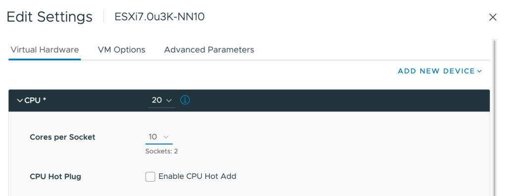
Once everything was set up and the ESXi host was operational, I checked to see if I could deploy a 16 vCPU VM to simulate particular NUMA client configuration behavior and verify the CPU environment.
The first command I use is to check the “physical” NUMA node configuration “sched-stats -t numa-node“. But this command does not give me any output, which should not happen.

Let’s investigate, let’s start off by querying the CPUinfo of the VMkernel Sys Info Shell (vsish): vsish -e get /hardware/cpu/cpuInfo
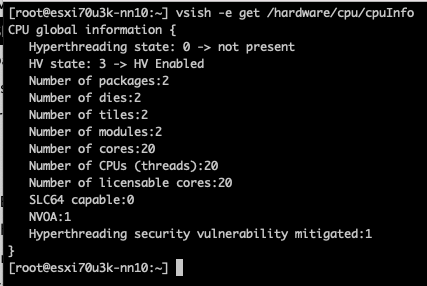
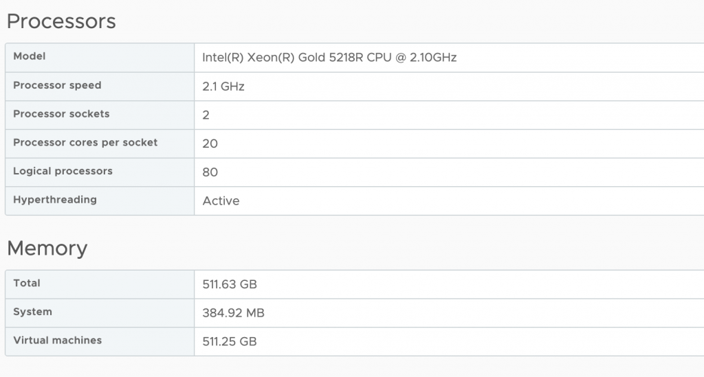
The ESXi host contains two CPU packages. The VM configuration Cores per Socket has provided the correct information to the ESXi kernel. The same info can be seen in the UI at Host Configuration, Hardware, Overview, and Processor.
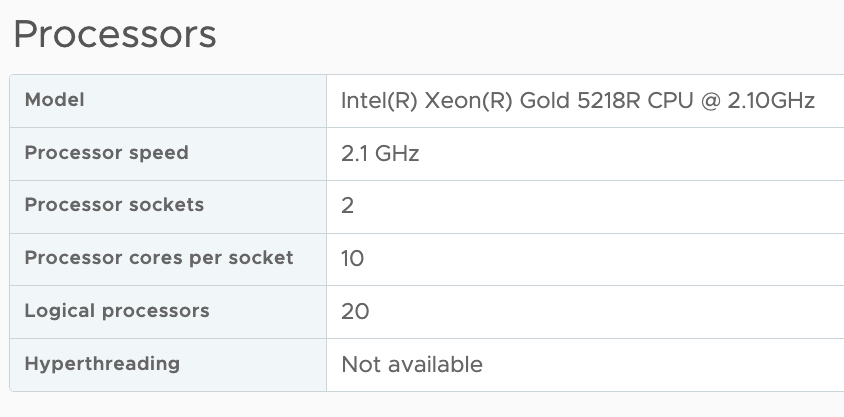
However, it doesn’t indicate the number of NUMA nodes supported by the ESXi kernel. You would expect that two CPU packages would correspond to at least two NUMA nodes. The command
vsish -e dir /hardware/cpuTopology/numa/nodes shows the number of NUMA nodes that the ESXi kernel detects

It only detects 1 NUMA node as the virtual NUMA client configuration has been decoupled from the Cores Per Socket configuration since ESXi 6.5. As a result, the VM is presented by the physical ESXi host as a single virtual NUMA node, and the virtual ESXi host picks this up. Logging in to the physical host, we can validate the nested ESXi VM configuration and run the following command.

vmdumper -l | cut -d \/ -f 2-5 | while read path; do egrep -oi "DICT.(displayname.|numa.|cores.|vcpu.|memsize.|affinity.)= .|numa:.|numaHost:." "/$path/vmware.log"; echo -e; done
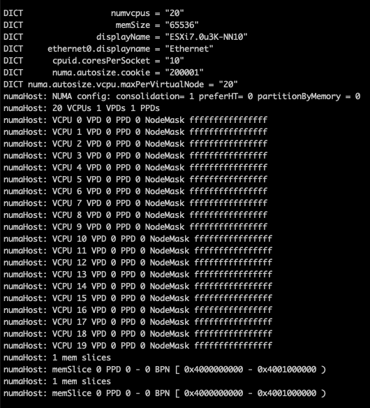
The screen dump shows that the VM is configured with one Virtual Proximity Domain (VPD) and one Physical Proximity Domain (PPD). The VPD is the NUMA client element that is exposed to the VM as the virtual NUMA topology, and the screenshot shows that all the vCPUs (0-19) are part of a single NUMA client. The NUMA scheduler uses the PPD to group and place the vCPUs on a specific NUMA domain (CPU package).

By default, the NUMA scheduler consolidates vCPUs of a single VM into a single NUMA client up to the same number of physical cores in a CPU package. In this example, that is 20. As my physical ESXi host contains 20 CPU cores per CPU package, all the vCPUs in my nested ESXi virtual appliance are placed in a single NUMA client and scheduled on a single physical NUMA node as this will provide the best possible performance for the VM, regardless of the Cores per Socket setting.

The VM advanced configuration parameter numa.consolidate = "false” forces the NUMA scheduler to evenly distribute the vCPU across the available physical NUMA nodes.
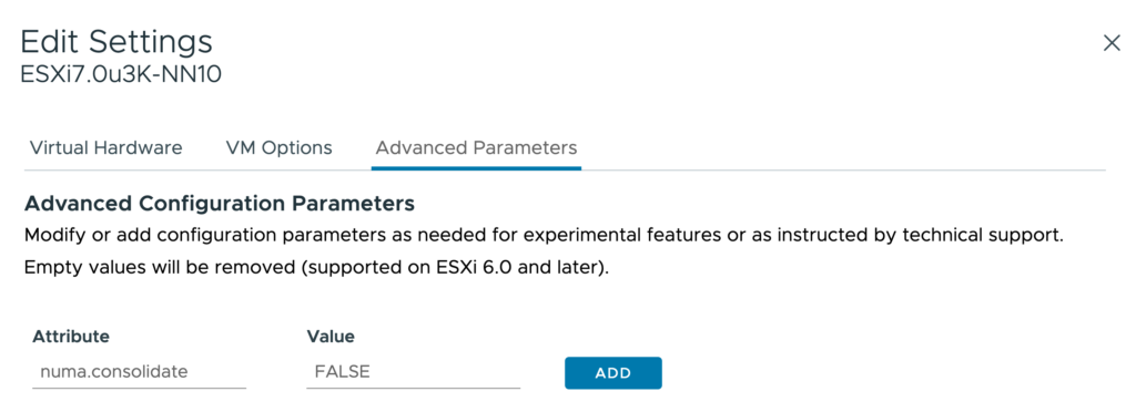
After running the vmdumper instruction once more, you see that the NUMA configuration has changed. The vCPUs are now evenly distributed across two PPDs, but only one VPD exists. This is done on purpose, as we typically do not want to change the CPU configuration for the guest OS and application, as that can interfere with previously made optimizations.
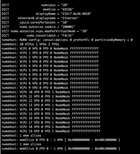
You can do two things to change the configuration of the VPD, use the VM advanced configuration parameter numa.vcpu.maxPerVirtualNode and set it to 10. Or remove the numa.autosize.vcpu.maxPerVirtualNode = “20” from the VMX file.

I prefer removing the numa.autosize.vcpu.maxPerVirtualNode setting, as this automatically follows the PPD configuration, it avoids mismatches between numa.vcpu.maxPerVirtualNode and the automatic numa.consolidate = "false" configuration. Plus, it’s one less advanced setting in the VMX, but that’s just splitting hairs. After powering up the nested ESXi virtual appliance, you can verify the NUMA configuration once more in the physical ESXi host:
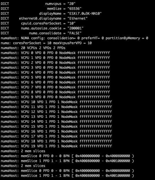
The vsish command vsish -e dir /hardware/cpuTopology/numa/nodes shows ESXi detects two NUMA nodes

and sched-stats -t numa-pnode now returns the information you expect to see

Please note that if the vCPU count of the nested ESXi virtual appliance exceeds the CPU core count of the CPU package, the NUMA scheduler automatically creates multiple NUMA clients.
Filed Under: NUMA Tagged With: VMware

vSphere 8 CPU Topology for Large Memory Footprint VMs Exceeding NUMA Boundaries

November 3, 2022 by frankdenneman

By default, vSphere manages the vCPU configuration and vNUMA topology automatically. vSphere attempts to keep the VM within a NUMA node until the vCPU count of that VM exceeds the number of physical cores inside a single CPU socket of that particular host. For example, my lab has dual-socket ESXi host configurations, and each host has 20 processor cores per socket. As a result, vSphere creates a VM with a vCPU topology with a unified memory address (UMA) up to the vCPU count of 20. Once I assign 21 vCPU, it creates a vNUMA topology with two virtual NUMA nodes and exposes this to the guest OS for further memory optimization.

You might have noticed that vNUMA topology sizing is structured around vCPU and physical core count. But what happens when the virtual machine configuration fits inside the NUMA node with its vCPU configuration, i.e., has less vCPU than the CPU has physical cores? But the VM requires more memory than the NUMA node can provide. I.e., the VM configuration exceeds the local memory configuration of the NUMA node.

As a test, I’ve created a VM with 12 vCPUs and 384GB. The vCPU configuration fits a single NUMA node (12<20), but the memory configuration of 384GB exceeds the 256GB of each NUMA node.

By default, vSphere creates the vCPU topology and exposes a unified memory address to the guest OS. For scheduling purposes, it creates two separate scheduling constructs to allocate the physical memory from both NUMA nodes but just doesn’t exposes that information to the guest OS. Inconsistent performance results from this situation, as the guest OS just starts to allocate the memory from the beginning of the memory range to the end without knowing anything about the physical origins. As a test, an application is running that allocates 380GB. As all the vCPU run in a single NUMA node, the memory scheduler will do its best and allocate the memory as close to the vCPUs as possible. As a result, the memory scheduler can allocate 226 GB locally (237081912 KB by vm.8823431) while having to allocate the rest from the remote NUMA node (155 GB).

Latency on an Intel for local NUMA nodes hovers around 73ns for a Xeon v4 and 89ns for a Skylake generation. At the same time, remote memory is about 130ns for a v4 and 139ns for a Skylake, AMD Epyc local is 129ns, and remote memory is 205ns. On Intel, that is a performance impact of 73% v4 and 56% on Skylake. On AMD, having to fetch remote memory will slow it down by 56%. That means, in this case, the application fetches 31% of its memory with a 73% latency penalty.

Another problem with this setup is that this VM is now quite an unbalanced noisy neighbor. There is little to do about monster VMs in your system, but this VM has an unbalanced memory footprint. It eats up most of the memory of NUMA node 0. I would rather see a more balanced footprint to utilize other cores on the NUMA node and enjoy local memory access. In this scenario, new virtual machines are forced to retrieve their memory from the other NUMA node if they are scheduled alongside this VM from a vCPU perspective.

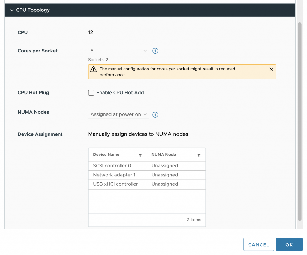
To solve this problem, we used to set the advanced setting “numa.consolidate = FALSE” in vSphere 7 and older versions. vSphere 8 provides the option to configure the vCPU topology and, specifically, the vNUMA topology from the UI that solves the aforementioned problem. In the VM options of the VM configuration vSphere 8 includes the option CPU Topology.

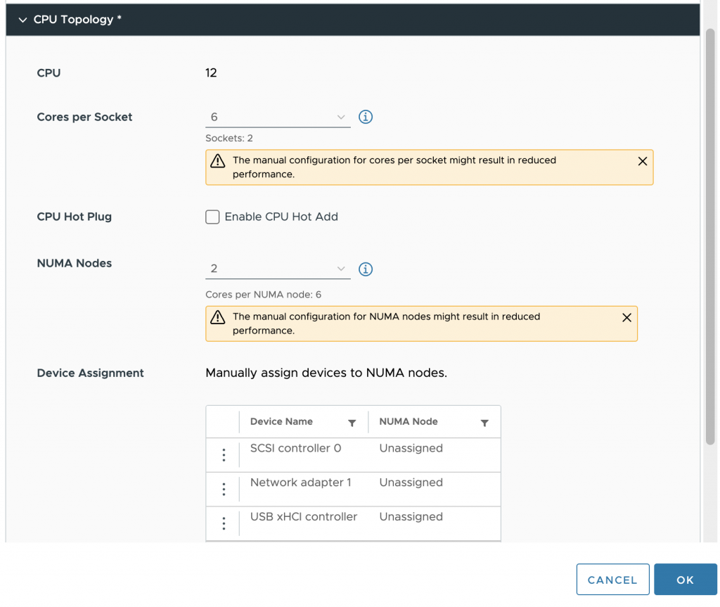
By default, the Cores per Socket and NUMA Nodes settings are “assigned at power on,” which is the recommended setting for most workloads. In our case, we want to change it, and first, we have to change the Cores per Socket settings before we can adjust the NUMA Nodes setting. It’s best to distribute the vCPUs equally across the physical NUMA nodes so that each group of vCPU can allocate an equal amount of memory capacity. The VM configuration is set to 6 cores per socket in our test case, creating two vSockets.

The next step is to configure the virtual NUMA nodes. Aligning this with the underlying physical configuration helps to get the best predictable and consistent performance behavior for the virtual machine. In our case, the VM is configured with two NUMA nodes.

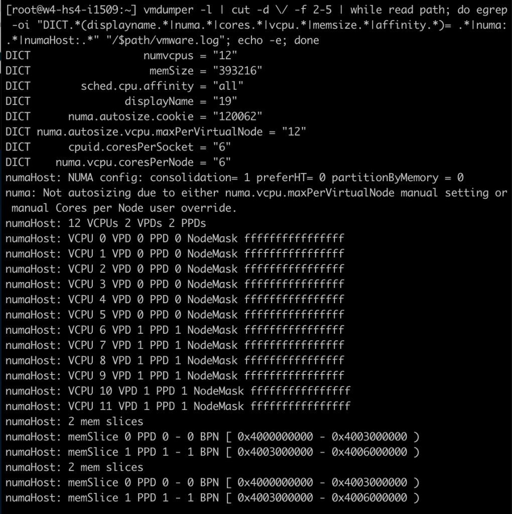
After the virtual machine is powered-on, I opened up a SSH session to the ESXi host and ran the following command: “vmdumper -l | cut -d \/ -f 2-5 | while read path; do egrep -oi “DICT.(displayname.|numa.|cores.|vcpu.|memsize.|affinity.)= .|numa:.|numaHost:.” “/$path/vmware.log”; echo -e; done”

That provided me with the following output; notice the following lines:
cpuid.coresPerSocket = “6”
numa.vcpu.coresPerNode = “6”
numaHost 12 VCPUs 2 VPDs 2 PPDs

It shows that the VM is configured with 12 vCPUs, 6 cores per socket, 6 vCPUs per NUMA node. At the ESXi scheduling level, the NUMA scheduler creates two scheduling constructs. A virtual proximity domain (VPD) is a construct used to expose a CPU topology to the guest OS. You can see that it has created two VPDs for this VM. VPD 0 contains VCPU 0 to VCPU 5, and VPD 1 contains VCPU 6 to VCPU 11. A PPD is a physical proximity domain and is used by the NUMA scheduler to assign a PPD to a physical NUMA node.

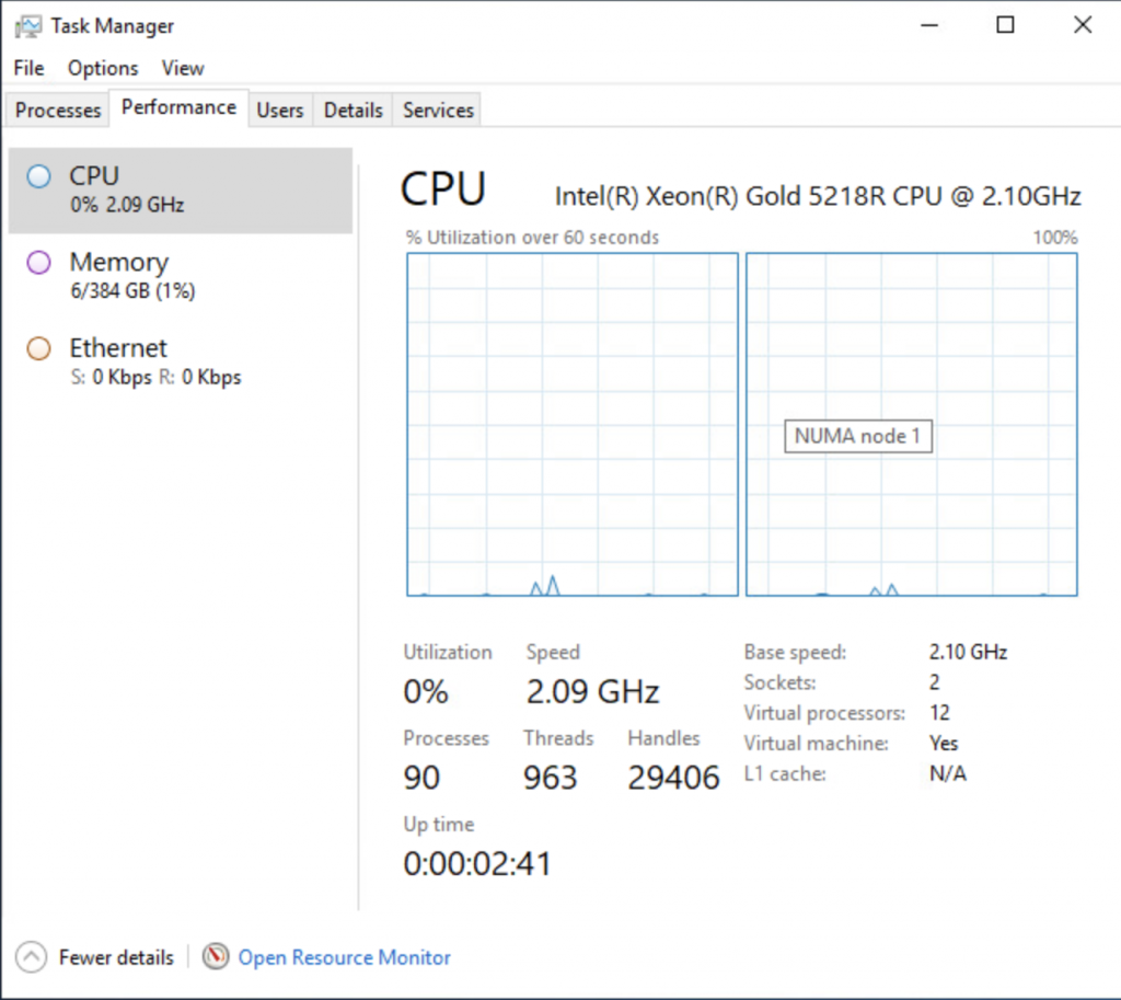
To check if everything has worked, I looked at the task manager of windows and enabled the NUMA view, which now shows two NUMA nodes.

Running the memory test again on the virtual machine shows a different behavior at the ESXi level. Memory consumption is far more balanced. The VMs NUMA client on NUMA node 0 is consuming 192 GB (201326592 KB), while the NUMA client of the VM on NUMA node 1 is consuming 189 GB (198604800 KB).

The vSphere 8 vCPU topology is a very nice method of helping manage VM configurations that are special cases. Instead of having to set advanced settings, a straightforward UI that can be easily understood by any team member that wasn’t involved with configuring the VM is a big step forward. But I like to stress once more that the default setting is the best for most virtual machines. Do not use this setting in your standard configuration for your virtual machine real estate. Keep it set to default and enjoy our 20 years of NUMA engineering. We got your back most of the time. And for some of the outliers, we now have this brilliant UI.

Filed Under: NUMA, Uncategorized

vSphere 8 CPU Topology Device Assignment

October 25, 2022 by frankdenneman

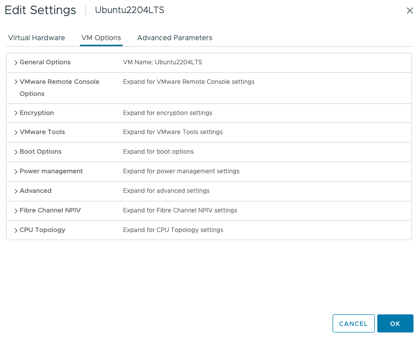
There seems to be some misunderstanding about the new vSphere 8 CPU Topology Device Assignment feature, and I hope this article will help you understand (when to use) this feature. This feature defines the mapping of the virtual PCIe device to the vNUMA topology. The main purpose is to optimize guest OS and application optimization. This setting does not impact NUMA affinity and scheduling of vCPU and memory locality at the physical resource layer. This is based on the VM placement policy (best effort). Let’s explore the settings and their effect on the virtual machine. Let’s go over the basics first. The feature is located in the VM Options menu of the virtual machine. 

Click on CPU Topology 

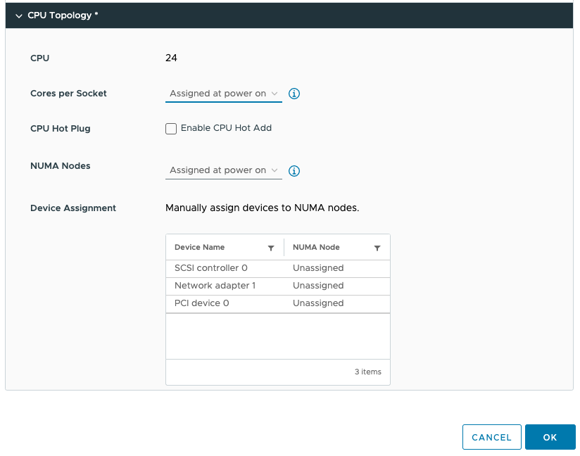
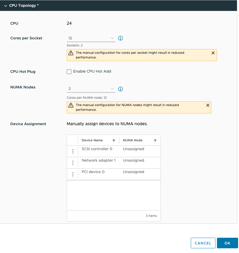
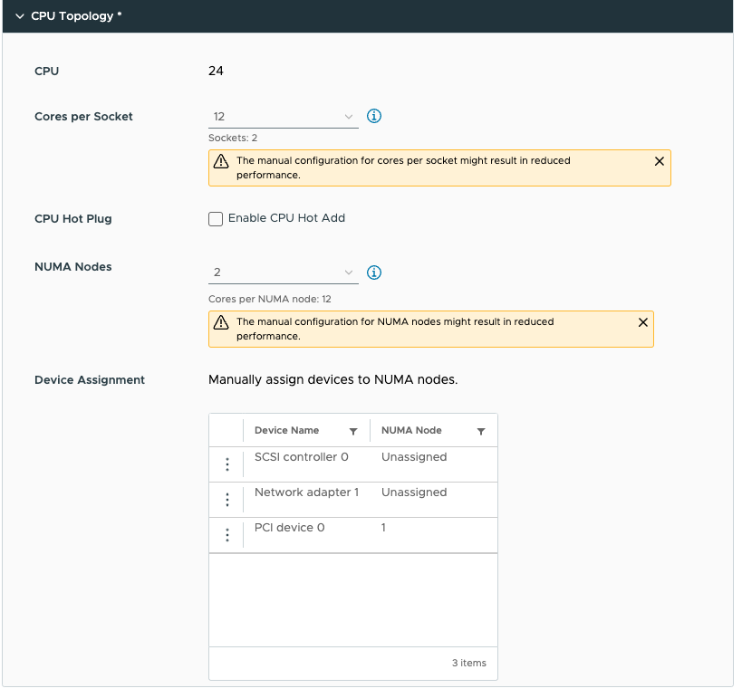
By default, the Cores per Socket and NUMA Nodes settings are “assigned at power on” and this prevents you from assigning any PCI device to any NUMA node. To be able to assign PCI devices to NUMA nodes, you need to change the Cores per Socket setting. Immediately, a warning indicates that you need to know what you are doing, as incorrectly configuring the Cores per Socket can lead to performance degradation. Typically we recommend aligning the cores per socket to the physical layout of the server. In my case, my ESXi host system is a dual-socket server, and each CPU package contains 20 cores. By default, the NUMA scheduler maps vCPU to cores for NUMA client sizing; thus, this VM configuration cannot fit inside a single physical NUMA node. The NUMA scheduler will distribute the vCPUs across two NUMA clients equally; thus, 12 vCPUs will be placed per NUMA node (socket). As a result, the Cores per Socket configuration should be 12 Cores per Socket, which will inform ESXi to create two virtual sockets for that particular VM. For completeness’ sake, I specified two NUMA nodes as well. This setting is a PER-VM setting, it is not NUMA Nodes per Socket. You can easily leave this to the default setting, as ESXi will create a vNUMA topology based on the Cores per Socket settings. Unless you want to create some funky topology that your application absolutely requires. My recommendation, keep this one set to default as much as possible unless your application developer begs you otherwise.

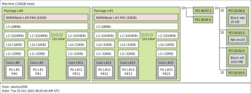
This allows us to configure the PCIe devices. As you might have noticed, I’ve added a PCIe device. This device is an NVIDIA A30 GPU in Dynamic Direct Path I/O (Passthrough) mode.  But before we dive into the details of this device, let’s look at the virtual machine’s configuration from within the guest OS. I’ve installed Ubuntu 22.04 LTS and used the command lstopo. (install using: sudo apt install hwloc)

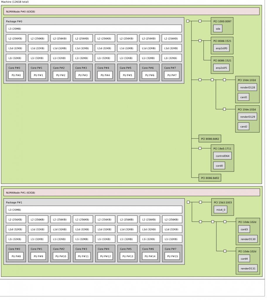
You see the two NUMA nodes, with each twelve vCPUs (Cores) and a separate PCI structure. This is the way a virtual motherboard is structured. Compare this to a physical machine, and you notice that each PCI device is attached to the PCI controller that is located within the NUMA node.

And that is exactly what we can do with the device assignment feature in vSphere 8. We can provide more insights to the guest OS and the applications if they need this information. Typically, this optimization is not necessary, but for some specific network load-balancing algorithms or machine learning use cases, you want the application to understand the NUMA PCI locality of the PCIe devices. 
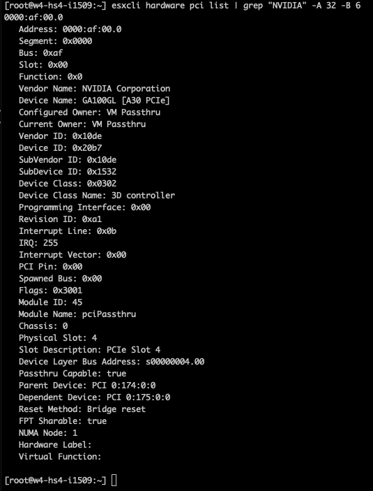
In the case of the A30, we need to understand its PCIe-NUMA locality. The easiest way to do this is to log on to the ESXi server through an SSH session and search for the device via the esxcli hardware pci list command. As I’m searching for an NVIDIA device, I can restrict the output of this command by using the following command “esxcli hardware pci list | grep “NVIDIA -A 32 -B 6”. This instructs the grep command to output 32 lines (A)after and 6 lines (B)before the NVIDIA line. The output shows us that the A30 card is managed by the PCI controller located in NUMA node 1 (Third line from the bottom).

We can now adjust the device assignment accordingly and assign it to NUMA node 1. Please note the feature allows you to also assign it to NUMA node 0. You are on your own here. You can do silly things. But just because you can, doesn’t mean you should. Please understand that most PCIe slots on a server motherboard are directly connected to the CPU socket, and thus a direct physical connection exists between the NIC or the GPU and the CPU. You cannot logically change this within the ESXi schedulers. The only thing you can do is to map the virtual world as close to the physical world as possible to keep everything as clear and transparent as possible. I mapped PCI device 0 (the A30) to NUMA node 1.

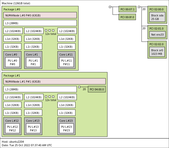
Running lstopo in the virtual machine provided me this result:

Now the GPU is a part of NUMA node 1. How we can confirm that is true is by taking the PCI device at address 04:00:00 given in the small green box that is inside Package 1 and seeing that is the same address as that given in the “esxcli hardware pci list” for the GPU – that is seen at the line titled “Device Layer Bus Address”  in that esxcli output. Because the virtual GPU device is now a part of NUMA node 1 the guest OS memory optimization can allocate memory within NUMA node 1 to store the dataset there so that it is as close to the device as possible. The NUMA scheduler and the CPU and memory scheduler within the ESXi layer attempt to follow these instructions to the best of their ability. If you want to be absolutely sure, you can assign NUMA affinity and CPU affinity at the lowest layers, but we recommend starting at this layer and testing this first before impacting the lowest scheduling algorithms.

Filed Under: CPU, Machine Learning, NUMA

Sub-NUMA Clustering

September 21, 2022 by frankdenneman

I’m noticing a trend that more ESXi hosts have Sub-NUMA Clustering enabled. Typically this setting is used in the High-Performance Computing space or Telco world, where they need to reduce every last millisecond of latency and squeeze out every bit of bandwidth the system can offer. Such workloads are mostly highly tuned and operate in a controlled environment, whereas an ESXi server generally runs a collection of every type of workload in the organization imaginable. Let’s explore what Sub-NUMA clustering does and see whether it makes sense if you should enable it in your environment.

NUMA

Most data center server systems are NUMA systems. In a NUMA system, each CPU contains its own memory controllers that provide access to locally connected memory. The overwhelming majority of systems in data centers worldwide are dual-socket systems. Each CPU has access to local memory capacity via its own memory controller, but it can also access the memory connected and controlled by the remote CPU. There is a difference in latency and bandwidth between reading and writing local and remote memory, hence the term Non-Uniform Memory Access (NUMA). 

AMD EPYC architecture is a Multi-Chip-Module (MCM) architecture and wildly differs from the monolithic architecture and its I/O path behavior. Sub-NUMA clustering is the functionality of partitioning Intel CPU packages. AMD provides similar functionality called NUMA per Socket (NPS). This article only focuses on Intel Sub-NUMA clustering technology as I have not seen server vendors’ default enablement of the NPS setting at this moment. 

Logical Partitions

The Intel E5-2600 processor family had a ring architecture, allowing Intel to optimize CPU core-to-memory access further. With the Haswell release (v3), Intel introduced Cluster-On-Die (COD) functionality. COD logically splits the CPU into two NUMA nodes. 

The COD feature reduces the search domain of the memory hierarchy. NUMA systems are cache-coherent. When a core generates a memory request, it checks its local L1 and L2 cache, the shared L3 cache (LLC), and the remote CPU cache. By splitting the CPU along its “natural” ring structure barrier, you end up with a smaller memory domain to search if there is a cache miss. And on top of that, you should have less local memory traffic if the applications and operating systems are NUMA optimized. Please look at the NUMA deep dive or read this research paper about COD caching structures for more info. The Skylake architecture (Intel Xeon Scalable Processors) moved away from the ring architecture and introduced a mesh architecture. The logical partition functionality remained and was introduced under a new name, Sub-NUMA Clustering (SNC). 

With SNC enabled, that previously shown dual CPU socket ESXi host system is now a four NUMA node system.

Comparing SNC to NUMA Performance 

Is SNC that Turbo feature that is hidden in your BIOS? If you look at the description some vendors use, you want to enable it immediately. Dell and Lenovo describe SNC: “…It improves average latency to the LLC”. I’m using the performance numbers that Hadar Greinsmark published in his research “Effective Task Scheduling of In-Memory Databases on a Sub-NUMA Processor Topology.” In a default NUMA configuration (SNC disabled), let’s look at the latency difference between Socket 0 (S0) and Socket 1 (S1).

Latency (ns)NUMA Node 0 (S0)NUMA Node 1 (S1)
NUMA Node 080.8138.9
NUMA Node 1139.779.9

With SNC enabled, Socket 0 contains two NUMA nodes, 0 and 1. Socket 1 contains NUMA Nodes 2 and 3. These logical partitions are genuine NUMA nodes. Although the different memory controllers and cache domains are on the same die, the caching mechanisms and non-interleaving of memory controllers create a non-uniform memory access pattern between the domains. Consequently, there is an increase in latency when fetching memory from the other “remote” NUMA node located within the same socket.

Latency (ns)NUMA Node 0 (S0)NUMA Node 1 (S0)NUMA Node 2 (S1)NUMA Node 3 (S1)
NUMA Node 0 (S0)74.2 (-7.5%)81.5 (+0.8%)132.0 (-5%)142.1 (+2.3%)
NUMA Node 1 (S0)82.0 (+1.4%)76.4 (-5.4%)135.6 (-2.4%)144.5 (+4%)
NUMA Node 2 (S1)132.4 (-5.2%)142.0 (+1.7%)73.6 (-7.9%)81.5 (+2%)
NUMA Node 3 (S1)136.0 (-2.6%)144.4 (+3.4%)81.5 (+2%)76.6 (-4.1%)

The SNC mapping method of memory addresses from the local memory controller to the closest LLC certainly works as the local NUMA latency with SNC drops on average between 6 to 7% compared to the default NUMA configuration. Take NUMA node 0 as an example. With SNC enabled, it experiences a memory latency of 74.2 ns; compared to SNC disabled, the access latency is 80.8 ns. As a result, SNC specifically reduces memory latency by 7.5% for NUMA node 0. 

The performance numbers show that remote connections handled by node 0 and node 2 are performing better than in the SNC disabled state, whereas NUMA node 1 and node 3 are performing less than in the SNC disabled state. The latency numbers reported to the remote node on the same socket are very interesting. It possibly shows the fascinating behavior of the interconnect architecture. However, Intel does not share detailed information about the Ultra Path Interconnect (UPI) framework. 

If we look at the architecture diagram, we notice that above NUMA node 0, a controller exists with two UPI connections. Above NUMA node 1, a controller is located with a single UPI connection. Possibly the single-UPI experiences more blocking I/O traffic on the mesh, whereas the UPI controller with two connections has more methods to manage the flow better.

But this is just pure speculation on my end. The latency shoots up if we look at the absolute remote I/O numbers. What matters is that workloads execute remote I/O operations if they cannot read or write memory locally. If it can find the memory in the NUMA node located on the same socket, it sees a latency increase of 8.6%. When it travels across the interconnect to a NUMA node in the other socket, the latency increases to 78.2%. When it needs to travel to the farthest NUMA node, latency almost doubles (90%). A default NUMA system has an average remote latency hit of 73%. But SNC has a more extensive performance spread as it improves up to 7% on average locally but also degrades remote memory access up to 5%. Let’s compare. In the default situation, local access is 80 ns, and remote access is 138.9 ns. With SNC, it has to deal with a worst-case scenario of 73.6 ns vs. 142.0. Which is the reason why the performance gap extends to 92.9%. And what decides what workload becomes local and remote? That is the key of this article. But before we dive into that, let’s look at bandwidth performance first. 

Bandwidth

Your Skylake CPU model has either two or three UPI links. Each UPI link is a point-to-point full duplex connection with separate lanes for each direction. A UPI link has a theoretical transfer speed of 10.4 Gigatransfers per second (GT/s), which translates to 20.8 gigabytes per second (GB/s). The Intel Xeon Platinum 8180 processor used in the report contains three UPI links, possibly providing an aggregated theoretical bandwidth of 62.4 GB/s. One controller has two UPI links, and the other controller has one UPI link. The research paper shows that when communicating with a remote node, the average bandwidth is roughly 34.4 GB/s. 

Speculation 

As limited information about UPI communication patterns is available, I assume the system uses only two UPI links in the default NUMA node. With default NUMA, memory interleaves across memory controllers; thus, memory has to be retrieved from both memory controllers, and therefore, the systems use both UPI controllers. Why it doesn’t use all three links, I think the overhead of syncing the I/O operation across three links and allowing other operations to use the interconnect outweighs the potential benefit of additional uplink. 

/speculation

But let’s stick to the facts. Here you see the impact of remote memory access. Bandwidth performance drops 69% when doing remote I/O on the default NUMA system. And for this exact reason, you want to have NUMA optimized workloads or right-sized virtual machines. Why doesn’t the progress bar move linearly on your screen? Possibly some non-NUMA optimized code fetching memory from the remote NUMA node. 

Bandwidth (MB/s)NUMA Node 0 (S0)NUMA Node 1 (S1)
NUMA Node 0111 08334 451
NUMA Node 134 455111 619

With SNC enabled, the system stops interleaving the whole memory range across both memory controllers within the CPU package and assigns each memory controller a subset of the memory range. Each memory controller has three channels, splitting the NUMA node’s bandwidth in half. The test system uses DDR4 2666 MHz (21.3 GB/s) memory modules, theoretically providing up to 63.9 GB/s per SNC NUMA node. When reviewing the research findings, the default NUMA node provided 111 GB/s (6 channels) by enabling SNC, which should result in approximately 55.5 GB/s per NUMA node. Yet the test results report 58 GB/s. SNC improves local bandwidth by an average of 4.5% due to the isolation of workload and, therefore, fewer blocking moments of other I/O operations on the mesh. Similar improvements occur for the NUMA node on the same socket.

Bandwidth (MB/s)NUMA Node 0 (S0)NUMA Node 1 (S0)NUMA Node 2 (S1)NUMA Node 3 (S1)
NUMA Node 0 (S0)58 08758 12334 25434 239
NUMA Node 1 (S0)58 14558 01334 26634 235
NUMA Node 2 (S1)34 28834 24858 06458 147
NUMA Node 3 (S1)34 28834 25458 14558 007

Therefore, SNC is a great way to squeeze out that last bit of performance for a highly tuned workload. If the workload fits inside the smaller NUMA node from a core count and memory capacity, it can expect a 7% improvement in latency and a 4% memory bandwidth. But, and there is a big but, but not the way Sir Mix-a-Lot likes it. But only if you deploy a scale-out workload. If you can deploy two workers in each worker node that run separate workloads, they both can benefit from extra obtainable bandwidth. If you only deploy a single workload, you’ve just robbed that workload of half its obtainable bandwidth. The workload can access remote memory capacity and possibly obtain more bandwidth. Still, it’s up to the NUMA scheduler or application’s discretion to make the smart move and choose the right NUMA node. And this is the point where we arrive at the fork in the road, the difference between a dedicated workload on bare metal and dealing with a NUMA scheduler that must take entitlement and workload patterns into account of multiple workloads.

SNC effectively reduces the per-NUMA node capacity and, thus, decreases the boundary of the single NUMA node virtual machine size. I have a question: Do 4% bandwidth improvement for scale-out the workload and 7% latency improvement sound like something you want to enable on a virtualization platform? How is a 10-vCPU VM placed on a dual socket with 18 cores per CPU package system?

Single NUMA node VM sizing

Not every application is NUMA aware. Most platform operators and admin teams attempt to “right-size” the virtual machine to circumvent this problem. Right-sizing means the VM contains fewer vCPUs and memory capacity than the CPU socket contains CPU cores and memory capacity, yet still can function correctly. With SNC, the NUMA node is split in half, resulting in smaller VMs if they need to fit inside a single NUMA node. 

vNUMA Topology

If a VM contains more vCPUs than a NUMA node contains CPU cores, the NUMA scheduler in ESXi creates a vNUMA topology for this VM and exposes this to the guest OS for NUMA optimizations. The NUMA scheduler creates multiple NUMA clients for this VM and places these accordingly, which is the key to understanding why SNC should or shouldn’t be enabled in your environment.

Initial placement

The NUMA scheduler gets an initial placement request if a VM is powered on or a virtual machine is migrated into the host via DRS. During the initial placement operation, the NUMA scheduler is aware of the distance between the NUMA nodes. And it will attempt to optimize the placement of the NUMA clients of the VMs. In other words, it attempts to place the NUMA clients as close to each other as possible. As a result, most of the time, if a VM consists of two NUMA clients, both NUMA clients are placed on NUMA nodes sharing the same socket with SNC enabled. 

Typically this happens during every synthetic test where this VM is the only VM running on the host; thus, the NUMA scheduler does not have to deal with contention or a complex puzzle or to fit these new clients amongst the other busy 44 other NUMA clients. 

NUMA load-balancing

The hypervisor is a very dynamic environment. The CPU scheduler has to deal with a variety of workload patterns, and there are workload patterns such as load correlation and load synchronicity. With load correlation, the schedulers must deal with the load spikes generated by the relationship between workloads running on different machines. The NUMA scheduler reviews the CPU load every 2 seconds to catch these patterns. For example, an application with a front-end VM communicates with a database. With load synchronicity workloads trend together, a VDI environment that spins up several desktops each morning will cause a persistent load spike. And so, the NUMA load-balancer might decide that it’s better to move some NUMA clients around the system. Getting into the NUMA load balancing algorithm’s details is too deep for this article. I’ve covered most in the NUMA deep dive. But the crucial thing to understand is that if it’s necessary to move the NUMA client, it will move the NUMA client, but it won’t take distance into account. The attempt will be the smartest thing to do for the system, but it might not always be the best for the VM. 

In many cases, If you would not enable SNC, that VM would have fit inside a single NUMA node, and no remote access occurred as it would fit a single NUMA node. With SNC, a large VM might be larger than the SNC-NUMA node size and thus is split up. It’s even worse if this VM connects to a PCIe device such as a GPU. Batch data transfers can occur across the interconnect, creating inconsistent data loading behavior during the host-to-device memory transfer operations. Learn more about NUMA PCI-e locality here.

SNC Enabled by Default

Why am I making this statement? I discovered that HP enabled SNC with the workload profiles “Virtualization – Max Performance” and “General Throughput Compute.”

ESXi does not have a setting in the UI that shows whether SNC is enabled or not, but we can apply the beautiful art form of deduction. By running the following (unsupported) command via SSH on the ESXi host:

echo "CPU Packages";vsish -e dir /hardware/cpu/packageList;echo "NUMA nodes";vsish -e dir /hardware/cpuTopology/numa/nodes

You get a list of the number of CPU packages (a fancy name for the device you can hold in your hand that contains the CPU cores, memory controllers, and PCI controllers) and the number of NUMA nodes in the system. If SNC is disabled, the number of NUMA nodes should equal the number of CPU packages. In this scenario, SNC is enabled. In most systems, you can enable and disable the setting individually, but if it’s part of a profile such as on the HP systems, you need to customize this. Dan tweeted the method to do this. 

Wrong on the HPE Side:https://t.co/XINRaD716y
"General Power Efficient Compute" is the default.
SNC = Disabled

I see SNC = Enabled on "Virtualization – Max Performance"
To change this but keep all other profile settings, set to Virt Max, Save, then Custom, then disable SNC.

— 🏴‍☠️ Dan (@Casper042) September 8, 2022

Disclaimer!

Please note that this tweet and this article are not official VMware recommendations to turn off SNC. This article will help you understand the implication of SNC on the overall behavior of SNC on the hardware layer and the way ESXi NUMA scheduler works. Always test a setting in your environment and your workload in a normal operating condition before changing a production environment.

My Personal Thoughts on SNC

I believe that SNC has very little to offer to a virtualization platform that runs all types of workloads. Workloads that range from tiny to monster VMs. If you have a dedicated vSphere platform running a specific low-latency workload that needs to run, for example, VOIP workload or High-Frequency Trading workload, then SNC makes sense. 

For the average vSphere environment that runs Oracle, SQL, or any high-performing database that needs lots of vCPUs, along with some front-end applications and a whole bunch of other frameworks, SNC will impact your performance. Most admins want the VM to fit inside a single NUMA node. SNC reduces the VM footprint. SNC taxes memory access more severely. Due to the increased gap between local and remote I/O, the user will detect an even more inconsistent feel of workload performance. The NUMA scheduler now needs to balance four smaller NUMA domains instead of two larger ones; thus, more decisions will be made that might not be optimal. Take Short-Term Migration, for example. The NUMA scheduler moves a VM to solve an imbalance between NUMA nodes. In that scenario, the scheduler migrates the vCPU immediately, but the memory follows more slowly. Since memory relocation is not immediate, remote memory access will temporarily increase while the pages migrate to the new NUMA node. With four smaller NUMA nodes to deal with, this can impact the overall user experience, especially if the gap between local and remote memory is enlarged from 69% to 90%.

VMs that could be Uniform Memory Access VM (fit inside a single NUMA node) now span multiple NUMA nodes. And as a result, we hope the guest OS and the application are NUMA optimized. Recent Linux optimization to their NUMA scheduler makes me hopeful, but keeping the host to default NUMA would avoid so many performance inconsistencies. 

In essence, It is my opinion that SNC is for the highly optimized, well-curated environment that has exploited every single trick in the book. It should not be the starting point for every virtualization platform. 

Want to learn more about NUMA? We spoke with the driving force behind NUMA optimizations at VMware in episode 19 of the Unexplored Territory Podcast. You can listen to the conversation with Richard Lu via the Unexplored Territory website, Apple Podcasts or Spotify

Filed Under: NUMA

Unexplored Territory Podcast Episode 19 – Discussing NUMA and Cores per Sockets with the main CPU engineer of vSphere

July 1, 2022 by frankdenneman

Richard Lu joined us to talk basics of NUMA, Cores per Socket, why modern windows and mac systems have a default 2 cores per socket setting, how cores per socket help the guest OS interpret the cache topology better, the impact of incorrectly configured NUMA and Cores per Socket systems and many other interesting CPU related topics. Enjoy another deep dive episode, you can listen to and download the episode on the following platforms:

Unexplored Territory website

Apple Podcasts

Spotify

Topics discussed in the episode

L1TF Speculative-Execution vulnerability

60 minutes of NUMA – VMworld session 2022

Extreme Performance Series: vSphere Compute and Memory Schedulers [HCP2583]

NUMA counters and command line tools – part 1

NUMA command lines tools – part 2

Filed Under: NUMA

  • Page 1
  • Page 2
  • Page 3
  • Interim pages omitted …
  • Page 6
  • Go to Next Page »

Copyright © 2025 · SquareOne Theme on Genesis Framework · WordPress · Log in