• Skip to primary navigation
  • Skip to main content

frankdenneman.nl

  • AI/ML
  • NUMA
  • About Me
  • Privacy Policy

vSphere ML Accelerator Spectrum Deep Dive for Distributed Training – Multi-GPU

May 12, 2023 by frankdenneman

The first part of the series reviewed the capabilities of the vSphere platform to assign fractional and full GPU to workloads. This part zooms in on the multi-GPU capabilities of the platform. Let’s review the full spectrum of ML accelerators that vSphere offers today. 

In vSphere 8.0 Update 1, an ESXi host can assign up to 64 (dynamic) direct path I/O (passthru) full GPU devices to a single VM. In the case of NVIDIA vGPU technology, vSphere supports up to 8 full vGPU devices per ESXi host. All of these GPU devices can be assigned to a single VM. 

Multi-GPU technology allows the data science team to present as many GPU resources to the training job as possible. When do you need multi-GPU? Let’s look at the user requirements. A data science team’s goal is to create a neural network model that provides the highest level of accuracy (Performance in data science terminology). There are multiple ways to achieve accuracy. One is by processing vast amounts of data. You can push monstrous amounts of data through a (smaller) model, and at one point, the model reaches a certain level of acceptable accuracy (convergence). Another method is to increase the sample (data) efficiency. Do more with less, but if you want to use data more efficiently, you must increase the model size. A larger model can use more complex functions to “describe” the data. In either scenario, you need to increase the compute resources if you push extreme amounts of data or push your datasets through larger models. In essence, Machine Learning scale is a triangle of three factors: data size, model size, and the available compute size. 

The most popular method of training a neural network is stochastic gradient descent (SGD). Oversimplified, it feeds examples into the network and starts with an initial guess. It trains the network by adjusting its “guesses” gradually. The neural network measures how “wrong” or “right” the guess is and, based on this, calculates a loss. Based on this loss, it adjusts the network’s parameters (weights and biases) and feeds a new set of examples. It repeats this cycle and refines the network until it’s accurate enough.

During the training cycle, the neural network processes all the examples in a dataset. This cycle is called an epoch. Typically a complete dataset cannot fit onto the GPU memory. Therefore data scientist splits up the entire dataset into smaller batch sets. The number of training examples in a single batch defines a batch size.

An iteration is a complete pass of a batch, sometimes called a step. The number of iterations is how many batches are needed to complete a single epoch. For example, the Imagenet-1K dataset contains 1.28 million images. Well-recommended batch size is 32 images. It will take 1.280.000 / 32 = 40.000 iterations to complete a single epoch of the dataset. Now how fast an epoch completes depends on multiple factors. One crucial factor is data loading, transferring the data from storage into the ESXi host and GPU memory. The other significant latency factor is the communication of gradients to update the parameters after each iteration in distributed training. A training run typically invokes multiple epochs. 

The model size, typically expressed in the parameter count, is interesting, especially today, where everyone is captivated by Large Language Models (LLMs). Where the AI/ML story mainly revolved around vision AI until a year ago, many organizations are keen to start with LLMs. The chart below shows the growth of parameters of image classification (orange line) and Natural Language Processing (blue line) in state-of-the-art (SOTA) neural network architectures. Although GPT-4 has been released, Microsoft hasn’t announced its parameter count yet, although many indicate that it’s six times larger than GPT-3. (1 Trillion parameters).

Why is parameter count so important? We have to look more closely at the training sequence. The article “Training vs. Inference – memory consumption by neural network” explores the memory consumption of parameters, network architecture, and data sets in detail. In short, a GPU has a finite amount of memory capacity. If I loaded a GPT-3 model with 175 Billion parameters using single-precision floating-point (FP32), it would need 700 GB of memory. And that’s just a static model consumption before pushing a single dataset example through. Quoting the paper “Efficient Large-Scale Language Model Training on GPU Clusters Using Megatron-LM,” “Training GPT-3 with 175 billion parameters would require approximately 288 years with a single V100 NVIDIA GPU.” With huge models, data scientists need to distribute the model across multiple GPUs. 

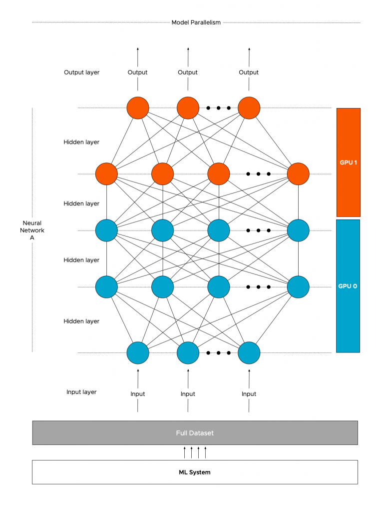
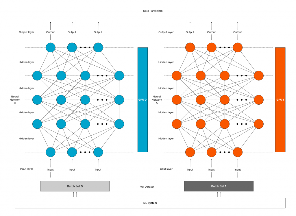
Data scientists sometimes prefer pushing more data through a smaller model than using a large model and dealing with model distribution. Regardless of model size, data distribution is the most common method of distributed learning. With this method, the entire model is replicated across multiple GPUs, and the dataset is split up and distributed across the pool of GPUs. Native data distribution modules are available in PyTorch and TensorFlow. 

With data distribution, the model is intact, but the dataset is split up. But to train the model coherently, the models must receive the result of each GPU’s training iteration. The models need to be trained in a certain lockstep; thus, the communication rate between the GPUs impacts the overall progression of the training job. The faster the GPUs communicate their learnings, the faster the model converges. It is why NVIDIA invests heavily in NVLINK and NVSwitch technology, and vSphere supports these technologies. Let’s look at the training process to understand the benefit of fast interconnects. 

To make sense of the behavior of distributed training, we need to look at how deep learning training on a single GPU works first. The data set is processed in batches to train a neural network, and we pass the data across the neural network. This process is called the forward pass, and it computes the error. The error indicates how wrong the neural network is as it compares the predicted label to the annotation (the gold-truth label). The next step for the ML framework is to run the backpropagation (backward pass), which runs the error back through the network, producing gradients for each parameter in the neural network. These gradients tell us how to learn from our errors, and the optimizer updates the parameters. And the neural network is ready for the next batch. It’s up to the data scientist to find the correct batch size to utilize as much GPU memory as possible while leaving enough room for the activations of the backward pass. For more detail: Training vs. Inference – memory consumption by a neural network.”

Now let’s look at the most popular form of distributed training, distributed data parallelism with Multi-GPU architecture utilizing a ring-AllReduce to share gradients optimally. In this scenario, the framework copies a replica of the neural network model to each GPU and splits the dataset across the multiple GPUs. Each GPU runs the forward and backward pass to compute the gradient for the processed batch subset. Now comes the interesting part, the gradients have to be shared across the GPUs as if all the GPUs have processed the complete batch. The most commonly used operation that shares the gradients between GPUs is called Gradient Ring-AllReduce. PyTorch DistributedDataParallel, Horovod, and TensorFlow Mirrored Strategy use this operation to compute the mean of the local gradients on all the GPUs and then update the model with the averaged global gradient. The optimizer updates the models’ parameters and processes the next batch of the data set.

The memory consumption of a model gradient mostly depends on the model architecture. It’s challenging to provide an average size of a typical model gradient. Still, a reasonable indication of a gradient size can be inferred from the number of parameters. The more parameters per model to update, the more data must be sent. Bandwidth between GPUs impacts how long it will take to send all this data. As models get larger and larger, so does the gradient size required to update the parameters during training. Larger batches generate larger gradients to update the model parameters in each training step. Let’s use the Bert-Large model as an example. It has 340 million parameters. Gradients use FP32 regardless of the forward pass numerical precision (BFLOAT16, FP16, FP32). As a result, each parameter requires 4 bytes (32 bits) of memory. The total memory required to store the gradient for all the parameters would be 320 million x 4 bytes = 1.36GB of data per iteration per GPU. The Ring-All Reduce method manages that each GPU receives an identical copy of the averaged gradients at the end of the backward pass to ensure that the updates to model parameters are identical. 

With Ring AllReduce, the GPUs are arranged in a logical ring, and each GPU receives data from its left neighbor and sends data to its right neighbor. The beauty of this ring structure is that each (N) GPU will send and receive values N-1. There are two steps involved, the scatter-reduce and the all-gather step. It would lengthen this article significantly if I covered the finer details of these steps, but what matters is that data is roughly transferred twice. So using the Ring AllReduce, each GPU training the Bert-Large must send and receive about 2.72GB of data per iteration. Using 25Gb Ethernet (providing 3.125 GB/s) 2.72GB *8 = 21.72Gb /25 Gbps = 870 milliseconds per iteration. This delay ramps up quite quickly if you run 30.000 iterations per epoch, and it takes 100 epochs to get the model accurate (convergence). That’s 725 hours or 30 days of latency. Bringing HPC Techniques to Deep Learning and Distributed data-parallel training using Pytorch on AWS are fantastic resources if you want to understand Ring AllReduce better.

Different configurations allow ML frameworks to consume multiple GPU devices. Multiple GPUs from a single ESXi host can be assigned to a VM for a single node-multi GPU setup. In a multi-node setup, multiple VMs are active and can consume GPUs from their local ESXi host. With different setups, there are different bandwidth bottlenecks. 

Coming back to the data-load process, it makes sense to review the bandwidth within the ESXi host to recognize the added benefit of specialized GPU interconnects. Internal host bandwidth ranges from high bandwidth areas to low bandwidth areas. High bandwidth areas are located on the GPU itself, where GPU cores can access High Bandwidth Memory (HBM) between 2 TB/s or 3.35 TB/s, depending on the form factor of the H100. The GPU device connects to the system with a PCIe Gen 5 interconnect, offering 126 GB/s of bandwidth, allowing the GPU to access ESXi host memory to read the data set or write the results of the training job. And suppose the distributed training method uses a multi-node configuration. In that case, the PCIe bus connects to the NIC, and data, such as gradients, are sent across (hopefully) a 25 Gbps connection equal to 3 GB/sec.

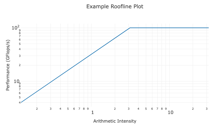
More complex models require more floating point operations per second (FLOPS) per byte of data. Thus, the combination of GPU processor speed and data loading times introduces an upper bound of the algorithm’s performance. Infra-tech savvy data scientists compute the limitations of the GPU hardware in terms of algorithm performance and visually plot this in a Roofline Model. 

Helping the data scientist understand which GPU models vSphere supports and how they can be connected to enable distributed training helps you build a successful ML platform. Selecting the correct setup and utilizing dedicated interconnects isolates this noisy neighbor, allowing the ESXi host to run complementary workloads. Let’s look at the different optimized interconnect technologies supported by vSphere for Multi-GPU distributed training. 

NVIDIA GPUDirect RDMA

NVIDIA GPUDirect RDMA (Remote Direct Memory Access) improves the performance of Multi-Node distributed training and is a technology that optimizes the complete path between GPUs in separate ESXi hosts. It provides a direct peer-to-peer data path between the GPU memory directly to and from the Mellanox NIC. It decreases GPU-to-GPU communication latency speeding up the workload. It alleviates the overall overhead of this workload on the ESXi Host as it avoids unnecessary system memory copies (and CPU overhead) by copying data to and from GPU memory. With GPUDirect RDMA, distributed training can now write gradients directly to each GPU input buffer without having the systems copy the gradients to the system memory first before moving it onto the sending NIC or into the receiving GPU. The HPC OCTO team ran performance tests comparing the data path between no-GPUDirect RDMA vs. GPUDirect RDMA setups. This test used a GPU as a passthrough device. GPUDirect RDMA supports both passthrough GPU and vGPU in 7.0U2.

One essential requirement is that the Mellanox NIC and the NVIDIA GPU must share the same PCIe switch or PCIe root complex. A modern CPU, like the Intel Scalable Xeon, has multiple PCIe controllers. Each PCIe controller is considered to be a PCIe root complex. Each PCIe root complex provides a dedicated connection to the connected PCIe devices, allowing for simultaneous data transfers between multiple devices. However, finding documentation about the PCIe slot to specific PCIe root complex mapping is challenging with most systems. Most server documentation only exposes PCIe slots to CPU mapping. Forget about discovering which PCIe slot is connected to which of one of the four PCIe root complexes a dual-socket Intel Scalable Xeon 4th generation server has. An easy way out is to place both PCIe cards on a PCIe riser card. When a PCIe device is installed on a PCIe riser card, it generally connects to the PCIe root complex associated with the slot where the riser card is installed. Please note CPUs are not optimized to work as PCIe switches, and if you are designing your server platform to incorporate RDMA fabrics, I recommend looking for server hardware that includes PCIe switches. Most servers dedicated to machine learning or HPC workload have PCIe switchboards, such as the Dell DS8440.

vSphere 7.0 u2 supports Address Translation Service (ATS) with Intel CPUs. ATS, part of the PCIe standard, allows efficient addressing by bypassing the IO Memory Management Unit of the CPU. If a PCIe device needs to access ESXi host memory, it must request the CPU translate the device memory address into a physical one. With ATS, the PCIe device, with the help of a translation agent, can directly perform the translation itself, bypassing the CPU and improving performance.

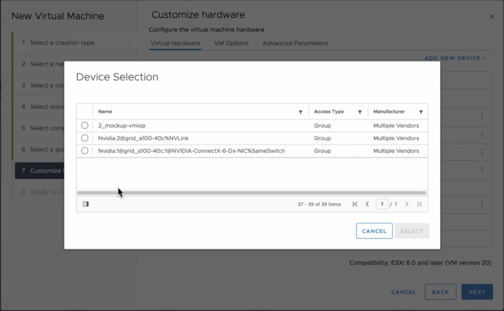
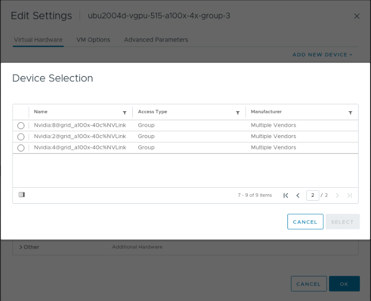
Device groups allow the VI-admin or operator to easily assign a combination of NVIDIA GPU and Mellanox NICs to a VM. vSphere performs a topology detection and exposes which devices share the same PCIe root complex or PCIe Switch in the UI. The device group in the screenshots shows two groups. The group listed at the top is a collection of two A100s connected via NVLink. The device group listed at the bottom combines an A100 GPU, using a 40c vGPU profile (a complete assignment of the card) and a Mellanox ConnectX-6 NIC connected to the same Switch. I must admit that the automatically generated device group names can be a bit more polished.

Communication backends such as NCCL, MPI (v1.7.4), and Horovod support GPUDirect RDMA.

NVIDIA NVLink Bridge

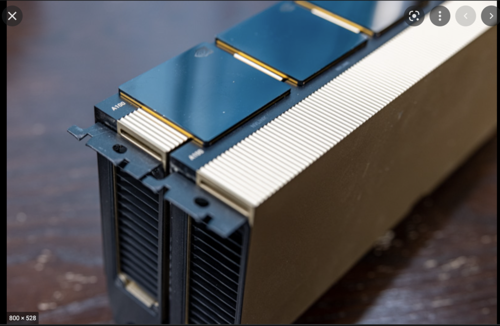
NVLink is designed to offer a low-latency, high-speed interconnect between two adjacent GPU devices to improve GPU-to-GPU communications. NVLINK Bridge is a hardware interconnection plug that connects two PCIe GPUs. The photo shows two PCIe A100 GPUs connected by three NVlink bridges. Using an NVLink setup requires some planning ahead, as the server hardware should be able to allocate two double PCI slot cards directly above each other. It rules out almost every 2U server configuration.

For all peer-to-peer access, data flows across the NVLink connections. The beauty is that the CUDA API enables peer access if both GPUs can access each other over NVLINK, even if they don’t belong to the same PCIe domain managed by a single PCI root complex. The P100 introduces the first generation of NVlink, and the H100 has the latest generation incorporated in its design. Each generation increases its links per GPU and, subsequently, the total bandwidth between the GPUs.

NVLink Specifications2nd Gen3rd Gen4th Gen
Maximum Number of Links per GPU61218
NVLink bandwidth per GPU300 GB/s600 GB/s900 GB/s
Supported GPU ArchitecturesVolta GPUsAmpere GPUsHopper GPUs

The fourth generation offers up to 900 GB/s of bandwidth between GPUs, creating an interesting bandwidth landscape within the system. The PCIe connection is used when the dataset is loaded into GPU memory. In CUDA terminology, this is referred to as a host-to-device copy. Each GPU has its memory address space, so the data set flows to each GPU separately across its PCIe connection. The GPU initiates direct memory access for this process. When models need to synchronize, such as sharing or updating gradients, they use the NVLink connection. In addition to the bandwidth increase, latency is about 1/10th of the PCie connection (1.3 ms vs. 13 ms). An upcoming article covers DMA and memory-mapped I/O extensively. 

But what about if you want to integrate four PCIe GPUs in a single ESXi host system? vSphere 7 and 8 support the number of GPUs but do not expect scalable linear performance when assigning all four GPUs to a single VM, as NVLink works per bridged card pair. Synchronization data of machine learning models between the pairs traverse across the PCIe bus, creating a congestion point. Going back to Ring-AllReduce, all the transfers happen synchronously. Thus the speed of the allreduce operation is limited by the connection with the lowest bandwidth between adjacent GPUs in the ring. For these configurations, it makes sense to look at HGX systems with 4 GPUs connected to NVLink integrated into the motherboard and using SXM-type GPUs or 8-GPU systems with an integrated NVSwitch. 

NVSwitch

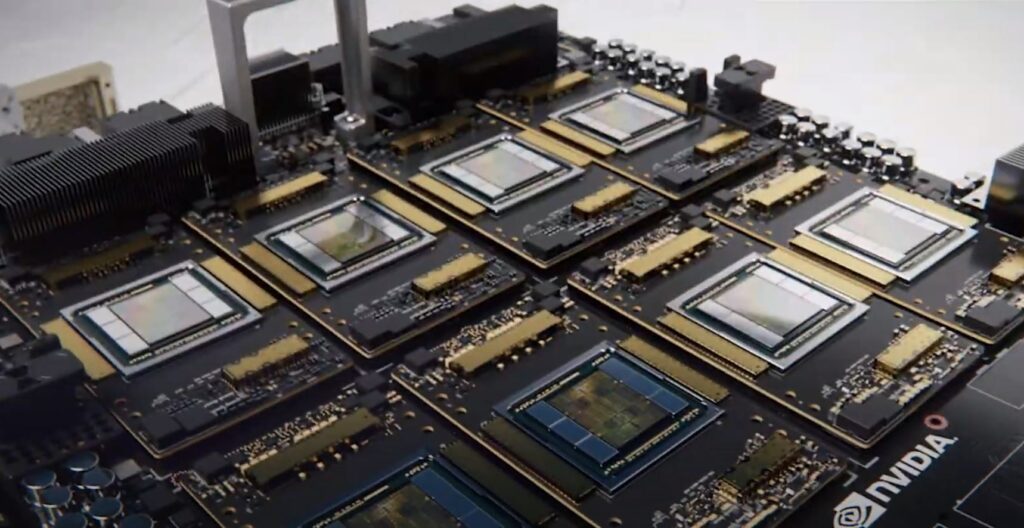
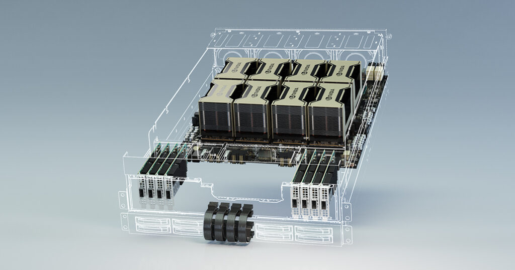
vSphere 8.0 Update 1 supports up to 8 vGPU devices connected via an NVSwitch fabric. An NVSwitch connects multiple NVLinks providing an all-to-all communication and single memory fabric. NVSwitch fabrics are available in NVIDIA HGX-type systems and use GPUs with the SXM interface. The Dell PowerEdge XE8545 (AMD) (4 x A100), XE9680 (8 x A100\H100) (Intel), and HPE Apollo 6500 Gen10 Plus (AMD) are such systems. If we open up an HGX machine, the first thing that sticks out is SXM from factor GPU. It moves away from the PCIe physical interface. The SXM socket handles power delivery, eliminating the need for external power cables, but more importantly, it results in a better (horizontal) mounting position, allowing for better cooling options. A H100 SXM5 also runs more cores (132 streaming multi-processors (SMs)) vs. H100 PCIe (113 SMs).

When the data arrives at the onboard GPU memory, after a host-to-device copy, communication remains between GPUs. All communication flows across the NVLinks and NVswitch fabrics, essentially keeping GPU-related traffic of the CPU interconnect (AMD Infinity fabric, Intel UPI ~40 GB/s theoretical bandwidth). 

With the help of vSphere device groups, the vi-admin or operator can configure the virtual machines with various vGPU configurations. They can be assigned in groups of 2, 4, and 8. Suppose a device group selects a subset of GPU devices of the HGX system. In that case, vSphere isolates these GPUs and disables the NVlink connections to the other GPUs, offering complete isolation between the device groups.

No virtualization tax

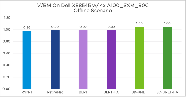
One of the counterarguments I face when discussing these technologies with tech-savvy data scientists is the perception of overhead. Virtualization impacts performance. Why inject a virtualization layer if I can run it on bare metal? Purely focusing on performance, I can safely say this is a thing of the past. MLCommons (an open engineering consortium that aims to accelerate machine learning innovation and its impact on society) has published the MLPerf v3.0 results. The performance team ran MLPerf Inference v3.0 benchmarks on Dell XE8545 with 4x virtualized NVIDIA SXM A100-80GB and Dell R750xa with 2x virtualized NVIDIA H100-PCIE-80GB, both with only 16 vCPUs out of 128. The ESXi host runs the ML workload while providing ample room for other workloads.

For the full write-up and more results, please visit the VROOM! Performance Blog.

What is interesting is that NVIDIA released a GPU designed to accelerate inference workloads for generative AI applications. The H100 NVL for Large Language Model Deployment contains 188GB of memory and features a “transformer engine” that can deliver up to 12x faster inference performance for GPT-3 compared to the prior generation A100 at data center scale. It is interesting that NVIDIA now sells H100 directly connected with NVLinks as a single device. It promotes the NVLink as a first-class building block instead of an article that should be ordered alongside the devices. 

With that in mind, the number of available devices is incredibly high. Each with its unique selling points. The following article overviews all the available and supported GPU devices.

Other articles in this series:

  • vSphere ML Accelerator Spectrum Deep Dive Series
  • vSphere ML Accelerator Spectrum Deep Dive – Fractional and Full GPUs
  • vSphere ML Accelerator Spectrum Deep Dive – Multi-GPU for Distributed Training
  • vSphere ML Accelerator Spectrum Deep Dive – GPU Device Differentiators
  • vSphere ML Accelerator Spectrum Deep Dive – NVIDIA AI Enterprise Suite
  • vSphere ML Accelerator Spectrum Deep Dive – ESXi Host BIOS, VM, and vCenter Settings
  • vSphere ML Accelerator Spectrum Deep Dive – Using Dynamic DirectPath IO (Passthrough) with VMs
  • vSphere ML Accelerator Spectrum Deep Dive – NVAIE Cloud License Service Setup

Filed Under: AI & ML Tagged With: GPU, Machine Learning

vSphere ML Accelerator Deep Dive – Fractional and Full GPUs

May 10, 2023 by frankdenneman

Many organizations are building a sovereign ML platform that aids their data scientist, software developers, and operator teams. Although plenty of great ML platform services are available, many practitioners have discovered that a one-size-fits-all platform doesn’t suit their needs. There are plenty of reasons why an organization chooses to build its own ML platform; it can be as simple as control over maintenance windows, being able to curate their own toolchain, relying on a non-opinionated tech stack, or governance/regulations reasons. 

The first step is to determine the primary workload. Will this be only inference, training, or a mix of both? Getting some servers and a few GPU resources might sound like a good start, but understanding the workload in more detail allows you to get the right resources and create a relevant and valuable platform. 

If your organization plans to purchase ML-assisted products and services, the focus shifts towards deploying an “inference” workload. Inference workloads are production-ready machine models infused in services or applications that process unseen data and generate an action for the subsequent business process or a recommendation. These workloads require the appropriate hardware and orchestration services. Only a monitoring suite focusing on service availability could suffice if the models are vendor-proprietary. 

If your organization builds models, the ML platform should focus on two distinct disciplines: Model development and model deployment. A term often heard in this scenario is MLOPs, DevOPs for the Machine Learning ecosystem. The ML platform should provide an infrastructure and software platform that helps data scientists develop their models. Data Scientists are highly skilled in calculus, linear algebra, and statistics. They are typically not hardcore developers, nor are they infrastructure-tech savvy. The unicorns are the ones that know enough to help themselves with creating their own world and developing their model. This blog series and the training vs. inference series intend to bring you closer to the data science team and help you understand some of the nuances of machine learning without going through a full-fledged linear algebra course. 

ML Development Lifecycle

A machine learning model that is fully trained and deemed production ready must be deployed. It cannot run in thin air. It needs to be incorporated into a service or an application. A model is never a standalone feature; thus, developers are needed after the data scientist is done with this model version. And therefore, you need developers ready to incorporate the model into a software system, deploy it, and scale it to serve the inference requests. Software tools are needed to build, test, release, deploy, and monitor these ML-assisted services. The model development lifecycle or ML project work-flow is typically categorized into three broad areas:

  1. Build process
  2. Training process
  3. Deployment process

In the build process, the data science team determines what framework and algorithm to use during the concept phase. They explore what data is available, where the data lives, and how they can access it. They study the idea’s feasibility by running some tests using small data sets.

In the training process, the data science team limited the possible algorithms and trained the models to learn from the data. Based on the training process results, the model is tuned and retrained. The training process can be cyclical and include various steps from the built process, such as finding more data, as the current dataset might not be satisfactory. 

The deployment process is where the model is moved into production. It’s now available to the user and processes unseen data. Models facing human behavior tend to deteriorate over time at a much faster rate than models built to augment or support closed-mechanical looped systems. Simply as human nature changes over time and thus the model will slowly detect fewer patterns, it’s trained to recognize. For these models, a recurring training loop must be created where production data is captured, prepared as new datasets to train the model and replace the old model with a freshly trained one. 

To successfully integrate, deploy, operate, monitor and retrain and re-release, you must create a platform that allows DevOps and Machine Learning teams to develop together. This is where MLOPs platforms add tremendous value to the parties involved. Mix this with an ML-savvy VI-admin and operator team, and this group can help the organization achieve its goals. This series covers the features and functionalities of the ML accelerators available in vSphere and how to set them up in vSphere and Tanzu Kubernetes Grid Services. Articles about MLOps platforms are planned for later this year. 

Understanding the three ML processes better is essential for the infrastructure focussed operator, as this translates to hardware requirements. Let’s look at what’s supported by vSphere first and then map these features and functionalities to the ML development lifecycle processes. vSphere and Tanzu Kubernetes Grid Services can assign ML accelerators (GPUs) to workloads. Three configurations are possible: a full GPU, a fractional GPU, and multiple GPUs assigned to a single VM. Fractional GPU functionality allows vSphere to split up a full GPU and assign smaller GPUs to multiple VMs. With Multi-GPU, the ESXi hosts can assign multiple GPUs to VMs. NVIDIA GPUDirect RDMA technology significantly improves communication between GPU-enabled VMs on different ESXi hosts. Throughout this series, we will continuously dive deeper into each technology.

Full GPUs

vSphere allows assigning a full GPU to a VM. Either by using VMware’s (Dynamic) Direct Path I/O technology (Passthru) or NVIDIA’s vGPU technology. This full GPU is exclusively available for this workload. No sharing between VMs is possible. (Dynamic) Direct Path I/O provides VMs access to the physical functions of the GPU device with the help of Memory Mapped I/O. One of the articles in this series covers this topic in detail. The difference between Dynamic Direct Path I/O and Direct Path I/O is the method of assigning the device to the VM. Direct Path I/O assigns the GPU Device to the VM based on the PCIe address of the device. In contrast, Dynamic Direct Path I/O uses a key-value method using either custom or vendor-device generated labels. This allows vSphere to decouple the static relationship between VM and device and provides more flexibility for initial placement processes used by DRS and HA. By default, vSphere 8 uses Dynamic Direct Path I/O with vendor-generated labels.

NVIDIA vGPU builds on Dynamic Direct Path I/O and installs the NVIDIA vGPU Manager in the kernel. It allows for creating fractional GPUs and makes vMotion possible. And this is where the choice between both technologies becomes interesting when assigning a full GPU.

Direct Path I/ODynamic Direct Path I/ONVIDIA vGPU
Failover HANoYesYes
Initial Placement DRSNoYesYes
Load Balance DRSNoNoNo
vMotionNoNoYes
Host Maintenance ModeShutdown VMCold MigrationManual vMotion
SnapshotNoNoYes
Suspend and ResumeNoNoYes
Fractional GPUsNoNoYes
TKGS VMClass SupportNoYesYes

In both scenarios, dynamic direct path I/O and vGPU allow assigning a dedicated GPU to a VM, which can help the data science team achieve their goals in the build, train or deploy process. But often, more elegant, more efficient technologies are available that create a suitable environment for the workloads but increase overall resource availability within the platform, ready for the data science teams to utilize.

Fractional GPUs

Fractional GPUs enable multiple VMs to have simultaneous, direct access to a single physical GPU by partitioning a physical GPU device into multiple smaller GPU instances. This functionality is provided by NVIDIA Virtual GPU technology and is available on data center class GPUs and a subset of NVIDIA RTX GPU devices. A vGPU device supports multiple vGPU types that are optimized for specific workloads. The vGPU types applicable for machine learning workloads are C-series and Q-series. 

The C-series is optimized for compute-intensive workloads. These are pretty much the classical ML workloads. The Q-series type can do the same, but the key difference is that the C-type can only decode video streams, and the Q-type can also (hardware) encode video streams. This difference is essential to know if the data science team plans to deploy a vision AI model. If the model only generates an action or a warning after object\anomaly detection in a video stream, the video is not encoded, and thus only decoders are necessary. A C-series vGPU type is sufficient. However, if the video stream is encoded after being processed by the model because human intervention or a second opinion is required, then a Q-type series is required.

NVIDIA vGPU offers two modes, the default Time-sliced mode or the vGPU Multi-Instance GPU (MIG) mode, available from the Ampere architecture onwards. A vGPU is assigned to a VM by selecting a vGPU type (C or Q-series) and a frame buffer size (GPU memory). When using MIG mode, the vGPU type also provides the ability to specify compute elements. The GPU device runs either in time-sliced mode or in MIG mode. There is no possibility of creating a heterogenous vGPU environment where MIG and time-sliced profiles share the same physical GPU device. You can deploy multiple GPU devices in one ESXi host and configure one GPU in time-sliced mode and one in MIG mode. 

The number of C and Q-series vGPU types are GPU type dependent. For example, an A100 40GB allows ten time-sliced C-Series with a 4GB frame buffer per instance type. In comparison, the A100 80GB allows twenty instances of the same configuration. The A30 and A100 only have video encoders onboard, not video decoders. There is no Q-series vGPU Type available for the A100. A time-sliced vGPU type provides exclusive use of the configured frame buffer until the VM is destroyed. Interesting to note is that the frame buffer cannot be over-allocated. Thus a 40 GB GPU will only accept five VMs with an 8GB frame buffer. Attempting to power on the sixth VM with an 8GB frame buffer fails. Even if all the VMs are idle.

The GPU best effort scheduler coordinates access to the GPU device, allowing active workloads to utilize all the compute architecture, such as decoders (NVDEC), encoders (NVENC), and copy engines (CE) on the GPU device. If multiple VM access the GPU, the scheduler schedules these workloads serially. A time slice determines the time window a vGPU can generate workload on the GPU before it is preempted and access is granted to another VM. It is based on the maximum number of vGPUs allowed for the vGPU type on that physical GPU. This is based on the total GPU memory and the assigned frame buffer per vGPU type. If the maximum number of vGPUs on that device is less than or equal to eight, then the time slice is 2 ms. The time-slice window is reduced to 1 ms if it’s more than eight. The scheduler round-robins the active workload. Thus if only one workload is active, the scheduler constantly assigns a time slice. The moment another workload activates, the scheduler adjusts. Most ML applications appreciate a more prolonged time slice as they require maximum throughput. NVIDIA allows for policy and time-slice adjustments. The following articles in this blog series cover the elements in the diagram (GPU Processing Clusters, Streaming Multiprocessors, MMIO space, BAR, etc.).

Time-shared Fractional GPU use case – The Build Process

If we return to the ML model development cycle, a time-sliced vGPU during the build process might be an excellent fit for most teams. They study the idea’s feasibility by running some tests using small data sets. As a result, the team will run and test some code, with lots of idle time in between. The typical run time is seconds to minutes for these code tests.

In many cases, the CPU provides enough power to run these tests. Still, if the data science team wants to research the effect and behavior of the combination of the ML model and the GPU architecture, a vGPU be beneficial. 

When looking at the situation from a platform operator perspective, this moment is where pooling and abstraction, two core tenets of VMware’s DNA, come into play. We can consolidate the efforts of different data science teams in a centralized environment and offer fractional GPUs. Sometimes a full GPU makes sense in these situations. But that is up to the discretion of the teams and organization. Fractional GPU provides tremendous benefits when used in the proper context.

Multi-Instance GPU vGPU 

Multi-instance GPU functionality is also great for the build process. It can create up to seven separate GPU partitions called instances by isolating the frame buffer, GPU cores, compute engines, and decoders. Predictable and consistent performance is the outcome of this strict isolation, and therefore MIG vGPUs are typically deployed to accelerate inference production workloads. 

Profile NameMemorySMsDecodersCopy EnginesInstances
MIG 1g.10gb1/81/7
0 NVDECs/0 JPEG/0 OFA
17
MIG 1g.10gb+m1/81/71 NVDEC/1 JPEG/1 OFA11
MIG 1g.20gb1/81/71 NVDECs/0 JPEG/0 OFA14
MIG 2g.20gb2/82/71 NVDECs/0 JPEG/0 OFA23
MIG 3g.40gb4/83/72 NVDECs/0 JPEG/0 OFA32
MIG 4g.40gb4/84/72 NVDECs/0 JPEG/0 OFA41
MIG 7g.80gbFullFull5 NVDECs/1 JPEG/1 OFA71

MIG provides a composable configuration of GPU resources. Although the profiles are pre-configured and cannot be changed, users can isolate the correct elements for the job. An A100 80GB GPU device contains seven GPU processing clusters (GPCs). Each GPC contains 16 streaming Multiprocessors (SMs). An SM contains L0 and L1 cache and four tensor cores that perform the needed FP16/FP32 mixed-precision fused multiply-add (FMA) operations and acceleration for all the data types (FP16, BF16, TF32, FP64, INT8, INT4). An A100 GPU contains ten memory controllers that offer access to five HBM2 stacks, which will be logically grouped into eight GPU memory slices. There are seven NVDECs (Video decoders), 7 NVJPGs (Image decoders), and one Optical Flow Accelerator (OFA). In total, there are seven copy engines. They are responsible for transferring data in and out of the GPU. 

For example, the MIG vGPU profile MIG4g.40gb constructs a GPU instance from four “GPU slices.” A GPU slice includes a “Sys Pipe,” a GPC, an L2 cache slice, and a GPU memory slice. A GPU memory slice includes the L2 cache slices and the associated frame buffer. These are dedicated memory resources. An application consuming a GPU instance does not consume an L2 slice from another GPU instance. This partitioning ensures fault isolation, error containment, recovery, and QoS.

The sys pipe communicates with the CPU and is responsible for GPC task scheduling. MIG creates a separate and isolated data path through the entire system, from the crossbar parts all the way to the memory controllers and its DRAM address buses. It’s expected that if more GPU memory is assigned to a GPU instance, more data is copied between the ESXi host system and GPU memory. Thus, dedicated copy engines are assigned to the GPU instance. Additionally, a dedicated number of decoders are assigned per GPU instance. Returning to the MIG Instance example, the MIG vGPU profile MIG4g.40gb isolates four of the eight available memory slices, four GPCs, four copy engines, and two decoders.

MIG provides a defined Quality of Service (QoS) and enhanced security due to isolation. Consistent performance throughout the vSphere cluster as consistent performance is maintained even if the VM is migrated to another ESXi host in the cluster. The vGPU is never impacted if another workload is saturating their GPU instance. In contrast, time-sliced provides a more dynamic environment, sometimes leading to better performance if the other GPU tenants are idling. However, there is no prioritization mechanism to indicate if a particular workload requires priority over others. Performance can be inconsistent. It depends on the activity of other tenants. Although MIG instances are hard-coded swimming lanes, and no other workload will dip in this pool of resources and internal pathways, the workload cannot go beyond its own swimming lane if the other MIG slices are idle. So there is no clear winner. Peak performance depends on the other GPU tenants, but if consistent performance is required, look no further than MIG technology. The Ampere and Hopper architecture provides MIG technology in specific data center GPUs. One of the following articles in the series depicts the availability of all the features in the supported vSphere and NVIDIA AI Enterprise (NVAIE) range.

MIG vGPU Fractional GPU use case – The Deployment Process

If we return to the ML model development cycle, the deployment phase requires consistent performance. Of course, there is no problem in assigning Full GPUs to the workload, but not every inference workload needs that many resources. MIG can offer the right amount of high-performing yet efficient technology. The training vs. inference series dove deep into both workload characteristics. For the typical inference workload, we notice a pattern of lightweight, latency-sensitive streaming data with lower computational needs than the training workload. 

TrainingInference
Data FlowBatch dataStreaming data
Storage CharacteristicsThroughput basedLatency-based, occasionally throughput
Batch SizeMany recommendations between 1-32
Smaller batch size reduces the memory footprint
Smaller batch size increases algorithm performance (generalization) 
Larger batch size increases compute efficiency
Larger batch size increases parallelization (Multi-gpu)
1-4
Data AccessRandom Access on a large data set
Multiple batches are prefetches to keep the pipeline full
Fast storage medium recommended
Fast storage and network recommended for distributed training
Streaming data
Memory FootprintLarge memory footprint
Forward propagation pass – backpropagation pass – model parameters
Long time duration of the memory footprint of activations (large bulk of memory footprint)
Smaller memory footprint
Forward propagation pass – model parameters
Activations are short-lived (Total memory footprint = est. 2 largest consecutive layers)
Numerical PrecisionHigher Precision RequiredLower Precision Required
Data TypeFP32
BF16
Mixed Precision (FP16+FP32)
BF16
INT8
INT4 (Not seen Often)

Training Process

For training workloads, it’s typically relatively straightforward present as many GPU resources to the training job as possible. The table shows that training is throughput based, requiring a large memory footprint, which often exceeds the memory capacity of a single GPU. 

Many data science teams explore distributed training methods to speed up training jobs to reduce training time duration. With today’s large models and large datasets, it’s common to see training jobs of 150+ hours (a whole week of continuous training). For these workloads, vSphere supports the latest and greatest technology available. VSphere 7 and 8 support assigning multiple physical GPUs to a single VM. NVIDIA technology provides high-speed interconnect technology to speed up inter-GPU communication during training jobs. Part 2 dives into the ML accelerator spectrum for distributed training – Multi-GPU technology. 

Other articles in this series:

  • vSphere ML Accelerator Spectrum Deep Dive Series
  • vSphere ML Accelerator Spectrum Deep Dive – Fractional and Full GPUs
  • vSphere ML Accelerator Spectrum Deep Dive – Multi-GPU for Distributed Training
  • vSphere ML Accelerator Spectrum Deep Dive – GPU Device Differentiators
  • vSphere ML Accelerator Spectrum Deep Dive – NVIDIA AI Enterprise Suite
  • vSphere ML Accelerator Spectrum Deep Dive – ESXi Host BIOS, VM, and vCenter Settings
  • vSphere ML Accelerator Spectrum Deep Dive – Using Dynamic DirectPath IO (Passthrough) with VMs
  • vSphere ML Accelerator Spectrum Deep Dive – NVAIE Cloud License Service Setup

Filed Under: AI & ML

vSphere ML Accelerator Spectrum Deep Dive Series

May 3, 2023 by frankdenneman

The number of machine learning workloads is increasing in on-prem data centers rapidly. It arrives in different ways, either within the application itself or data science teams build solutions that incorporate machine learning models to generate predictions or influence actions when needed. Another significant influx of ML workloads is the previously prototyped ML solutions in the cloud that are now moved into the on-prem environment, either for data gravity, governance, economics, or infrastructure (maintenance) control reasons. Techcrunch recently published an interesting article on this phenomenon.

But as an operator stuck between the data scientist, developer, and infra, you can be overwhelmed with the requirements that need to be met, the new software stack, and new terminology. You’ll soon realize that a machine-learning model does not run in a vacuum. It’s either integrated into an application or runs as a service. Training and running a model are just steps in applying machine learning to an organizational process. A software stack is required to develop the model, a software stack is required to train it, and a software stack is to integrate it into a service or application, and monitor its accuracy. Models aimed at human behavior tend to deteriorate over time. Our world changes, and the model need to adjust to that behavior. As a result, a continuous development cycle is introduced to retrain the model regularly.

It’s essential to understand the data science teams’ world to be successful as an operator. Building the hardware and software technology stack, together with a data science team, helps you to get early traction with other data science teams in the organization. As machine learning can be a shadow IT monster, it is vital to discover the needs of the data science teams. Build the infrastructure from the ground up, starting with the proper hardware ready to satisfy the requirements for training and inference jobs, and provide the right self-serving platform that allows data science teams to curate their own toolset that helps them achieve their goals.

To create the proper fundament, you need to understand the workload. However, most machine-learning content is geared toward data scientists. These articles primarily focus on solving an algorithmic challenge while using domain-specific terminology. I’ve written several articles about the training and inference workloads to overcome this gap.

Part 1: focuses on the ML Model development lifecycle

Part 2: Gives a brief overview of the pipeline structure

Part 3: Zooms into Training versus Inference Data Flow and Access Patterns

Part 4: Provides a deep dive into memory consumption by Neural Networks

Part 5: Provides a deep dive into Numerical Precision 

Part 6: Explores network compression technology in detail, such as pruning and sparsity.

Parts 3 to 6 offer detailed insights into the technical requirements of the neural networks during training jobs and the inference process. It helps to interpret GPU functionality and gauge the expected load of the platform.

To successfully accelerate the workload, I want to dive deeper into the available vSphere and Tanzu options in the upcoming series. It focuses on the available spectrum of machine learning accelerators the NVIDIA AI Enterprise suite offers. What hardware capabilities are available, and how do you configure the platform? Although this series focuses on GPUs, I want to note that CPUs are an excellent resource for light training and inference. And with the latest release of the Intel Sapphire Rapids CPU with its Advanced Matrix Extensions (AMX), the future of CPUs in the ML ecosystem looks bright. But I’ll save that topic for another blog post (series).

Articles in this series:

  • vSphere ML Accelerator Spectrum Deep Dive Series
  • vSphere ML Accelerator Spectrum Deep Dive – Fractional and Full GPUs
  • vSphere ML Accelerator Spectrum Deep Dive – Multi-GPU for Distributed Training
  • vSphere ML Accelerator Spectrum Deep Dive – GPU Device Differentiators
  • vSphere ML Accelerator Spectrum Deep Dive – NVIDIA AI Enterprise Suite
  • vSphere ML Accelerator Spectrum Deep Dive – ESXi Host BIOS, VM, and vCenter Settings
  • vSphere ML Accelerator Spectrum Deep Dive – Using Dynamic DirectPath IO (Passthrough) with VMs
  • vSphere ML Accelerator Spectrum Deep Dive – NVAIE Cloud License Service Setup

Filed Under: AI & ML

vSphere 8.0 Update 1 Enhancements for Accelerating Machine Learning Workloads

April 26, 2023 by frankdenneman

Recently vSphere 8 Update 1 was released, introducing excellent enhancements, ranging from VM-level power consumption metrics to Okta Identity Federation for vCenter. In this article, I want to investigate the enhancements to accelerate Machine Learning workloads. If you want to listen to all the goodness provided by update 1, I recommend listening to episode 40 of the Unexplored Territory Podcast with Féidhlim O’Leary (Spotify | Apple).

Machine learning is rapidly becoming an essential tool for organizations and businesses worldwide. The desire for accurate models is overwhelming; in many cases, the value of a model comes from accuracy. The machine learning community strives to build more intelligent algorithms, but we still live in a world where processing more training data generates a more accurate model. A prime example is the large language models (LLM) such as ChatGPT. The more data you add, the more accurate they get.

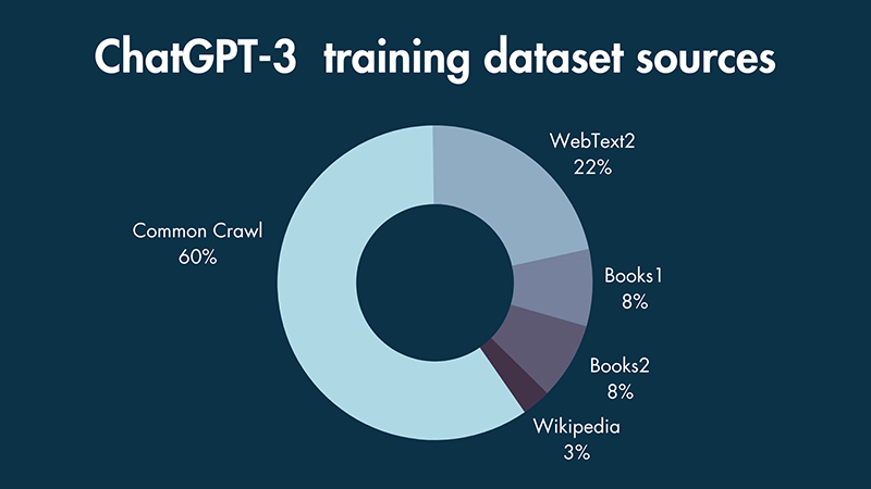
Source: ChatGPT Statistics (2023) — The Key Facts and Figures

To train ChatGPT, they used textual data from 5 sources. 60% of the dataset was based on a filtered version of data from 8 years of web crawling. I was surprised that 22% of that dataset came from Reddit posts with three or more upvotes (WebText2). But I digress. Large datasets need computation power, and our customers are increasing their machine learning accelerator footprint in their data centers. vSphere 8 update 1 caters to that need. vSphere 8 Update 1 provides the following enhancements focusing on Machine Learning workloads.

  1. Increase of PCI Passthrough devices per VM
  2. Support for NVIDIA NVSwitch
  3. vGPU VMotion Improvements
  4. Heterogeneous GPU Profile Support

The spectrum of ML Accelerators in vSphere 8 Update 1

Update 1 again increases the maximum number of PCI passthrough devices for a VM. In 7.0 with hardware version 19, 16 passthrough devices are supported. In 8.0, with hardware version 20, a VM can contain up to 32 passthrough devices. With 8.0 update 1, hardware version 20, vSphere supports up to 64 PCIe passthrough devices per VM.

vSphere 8 Update 1 extends the spectrum of ML accelerator by supporting NVIDIA NVSwitch Architecture. NVIDIA NVSwitch is a technology that bolts onto the system’s motherboard and connects four to sixteen SXM form factor GPUs. Such systems are known as NVIDIA HGX systems. The Dell PowerEdge XE8545 (AMD) (4 x A100), XE9680 (8 x A100\H100) (Intel), and HPE Apollo 6500 Gen10 Plus (AMD) are such systems. The HGX lineup consists of two platforms, the “Redstone” platform, which contains 4 x SXM4 A100 GPUs, and the “Delta” platform, which contains 8 x SXM4 A100 SXMe GPUs. With the introduction of the NVIDIA Hopper architecture, the HGX platforms are now called Redstone-Next and Delta-Next, containing SXM5 H100 GPUs. There is the possibility of connecting two baseboards of a Delta (-Next) platform via the NVSwitch together in a single server, providing the ability to connect sixteen A100/H100 GPUs directly, but I haven’t seen a server SKU of the major server vendors offering that configuration. If we open up an HGX machine, the first thing that sticks out is SXM from factor GPU. It moves away from the PCIe physical interface. The SXM socket handles power delivery, eliminating the need for external power cables, but more importantly, it results in a better (horizontal) mounting position, allowing for better cooling options. As the GPUs are better cooled, the H100 SXM5 can run more cores (132 streaming multi-processors (SMs)) vs. H100 PCIe (113 SMs).

What is the benefit of SXM, NVLINK, and NVSwitch?

Training machine Learning models require a lot of data, which the system has to move between components such as CPUs and GPUs and between GPUs and GPUs. Distributed training uses multiple GPUs to provide enough onboard GPU memory capacity to either process and execute the model parameters or to process the data set. If we dissect the data flow, this process has three major steps.

  1. Load the data from system memory on the GPUs
  2. Run the process (distributed training), which can initiate communication between GPUs
  3. Retrieve results from GPU to system memory.
  4. Rinse and repeat

Internal data buses move data between components, significantly affecting the system’s overall throughput. The most common expansion bus standard is PCI Express (PCIe). Its latest iteration (PCIe5) offers a theoretical bandwidth of 64 GB/s. That is fast, but nothing compared to the onboard GPU RAM speed of an A100 (600 GB/s) or an H100 (900 GB/s). To benefit the most from that memory speed is to build a non-blocking interconnect between the GPUs. If you go one level deeper, by creating a proprietary interconnect system, NVIDIA does not have to wait for the industry to develop and accept standards such as PCIe 6 or 7. It can develop and iterate much faster, attempting to match the interconnect speed to the high bandwidth memory speed of the onboard GPU RAM.

However, NVIDIA has to play well with others in the industry to connect the SXM socket to the CPU, and therefore the SXM4 (A100) connects to the CPU via a PCIe 4.0 x16 bus interface (source), and SXM5 (H100) connects to the CPU via a PCIe 5.0 x16 interface (source). That means that during a host-to-device memory copy, the data flows from the system memory across the PCIe controller to the SXM Socket with the matching PCIe bandwidth.

Suppose you are a regular ready of my content. In that case, you might expect me to start deep diving into PCIe NUMA locality and the challenges of having multiple GPUs connected in a dual-socket system. However, our engineers and NVIDIA engineers helped the NVIDIA library be aware of the home NUMA configuration. It uses CPU and PCIe information to guide the data traffic between the CPU and PCIe interface. When the data arrives at the onboard GPU memory, communication remains between GPUs. All communication flows across the NVLinks and NVswitch fabrics, essentially keeping GPU-related traffic of the CPU interconnect (AMD Infinity fabric, Intel UPI ~40 GB/s theoretical bandwidth). 

Please note, on the left side of the diagram, the NVLinks are greyed out of three GPUs to provide a better view of the NVLink connection of an individual GPU in an A100 HGX system.

GPU device-to-device communications occur across NVLinks and NVSwitches. An A100 GPU includes 12 3rd-generation NVLinks to provide up to 600 GB/sec bandwidth. The H100 increases the NVlinks to 18, providing 900 GB/sec, seven times the bandwidth of PCIe 5. With the help of vSphere device groups, the vi-admin can configure the virtual machines with various vGPU configurations. They can be assigned in groups of 2, 4, and 8. Suppose a device group selects a subset of GPU devices of the HGX system. In that case, vSphere isolates these GPUs and disables the NVlink connections to the other GPUs, offering complete isolation between the device groups.

At this moment, the UI displays quite a cryptic name. If we look at the image, we see Nvidia:2@grid_a100x-40c%NVLink. This name means that this is a group of two A100S with a 40C type profile (the entire card) connected via NVLink. Although the system contains eight GPUs, that doesn’t mean that vSphere only allows assigning multiple GPUs to virtual machines and TKGS worker nodes. Fractional GPU technologies, such as time-sliced or Multi-Instance GPU (MIG), are available. A later article provides a deep dive into NVIDIA Switch functionality. The beauty of this solution is that it uses vGPU technology, and thus we can live-migrate workload between different ESXi hosts if necessary. With each vSphere update, we introduce new enhancements to vGPU vMotion. vSphere 8 Update 1 offers two improvements to improve the utilization of high bandwidth vMotion networks.

vGPU vMotion Improvements

This new update introduces improvements to the internals of the vMotion process. Update 1 does not present any new buttons or functionalities to the user, but the vMotion internals are more aligned now with the high data load and high-speed transports.

A vGPU vMotion is a lot more complex than a regular vMotion, which by itself is still a magical thing in itself. With vGPU workloads, we have to deal with memory-mapped I/O and the situation that 100s of GPU stream processors access vGPU memory regions and can completely change multiple times within a second. An article about MMIO and GPUs will be published soon.

To cope with this behavior, we stun the VM so we can drain the memory as quickly as possible. The vMotion team significantly improved by moving checkpoint data to a more efficient vMotion data channel that can leverage multiple threads and sockets. In the previous configuration, the channel for transferring checkpoint data was fixed at two connections, while the new setup can consume as many TCP connections as the network infrastructure permits.

Additional optimizations are made to the communication process between the source and destination host to reduce “CPU Driven copies .”A more innovative method of sharing memory is applied, reducing the processes involved in getting the data over from the source host to the destination. With the help of vMotions stream multi-threaded architecture, vGPU vMotion can now saturate high-speed networks up to 80 Gbps.

Heterogeneous GPU Profile Support

Not necessarily a Machine Learning Workload enhancement, but it allows for a different method of GPU resource consumption, so there is some relationship worth mentioning. Before vSphere 8 Update 1, the first active vGPU workload determines the vGPU profile compatibility of the GPU device. For example, if a VM starts with a C-type vGPU profile with 12G on an NVIDIA A40, the GPU will not accept any other virtual machine with a 12A or 12Q profile. Although each of these profiles consumes the same amount of onboard GPU memory (frame buffer), the GPU rejects these virtual machines. With update 1, this is no longer the case. The GPU accepts different GPU types as long as they have identical frame buffer size configurations. And this makes one of the compelling use cases, “VDI by day, Compute by Night,” even more attainable. This flexibility does offer the ability to mix and match Q, C, and A workloads. The frame buffer size gap between B and the other profile types is too large to expect these profiles to run together on the same physical GPU. The largest B profile contains a 2 GB frame buffer.

vGPU Profile TypeOptimal Workload
Q-TypeVirtual workstations for creative and technical professionals who require the performance and features of Quadro technology
C-TypeCompute-intensive server workloads, such as artificial intelligence (AI), deep learning, or high-performance computing (HPC)
B-TypeVirtual desktops for business professionals and knowledge workers
A-TypeApp streaming or session-based solutions for virtual applications users

Source: Virtual GPU Software Documentation

vSphere 8 introduces a tremendous step forwards in accelerator resource scalability, from the ideation phase to big dataset training to securely isolating production streams of unseen data to tailored-sized GPUs. The spectrum of machine learning accelerators available in vSphere 8 update 1 allows organizations to cater to the needs of any data science team regardless of where they are within the life-cycle of their machine learning model development.

Filed Under: AI & ML

VMware Cloud Services Overview Podcast Series

April 17, 2023 by frankdenneman

Over the last year, we’ve interviewed many guests, and throughout the Unexplored Territory Podcast show, we wanted to provide a mini overview series of the VMware Cloud Services. Today we released the latest episode featuring Jeremiah Megie discussing the Azure VMware Solution.

Azure VMware Solution

Listen on Spotify or Apple.

VMware Cloud on AWS

In episode 013, we talk to Adrian Roberts, Head of EMEA Solution Architecture for VMware Cloud on AWS at AWS. Adrian discusses the various reasons customers are looking to utilize VMware Cloud on AWS, some of the challenges, and the opportunities that arise when you have your VMware workloads close to native AWS services.

Listen on Spotify or Apple.

Google Cloud VMware Engine

In episode 016, we talk to Dr. Wade Holmes, Security Solutions Global Lead at Google. Wade introduces Google Cloud VMware Engine, discusses various use cases with us, and highlights some operational differences between on-prem only and multi-cloud.

Listen on Spotify or Apple.

Oracle Cloud VMware Solution

In episode 023, we talk to Richard Garsthagen, Oracle’s Director of Cloud Business Development. Our discussion was all about Oracle Cloud VMware Solution. What is unique about Oracle Cloud VMware Solution compared to other solutions? Why does Richard believe this is a platform everyone should consider when you are exploring public cloud offerings?

Listen on Spotify or Apple.

Cloud Flex Storage

In episode 037, we talk to Kristopher Groh, Direct Product Management at VMware, responsible for various storage projects. Kris introduces us to Cloud Flex Storage and discusses the implementation in-depth. Kris also explains the different use cases for Cloud Flex Storage versus vSAN within VMware Cloud on AWS.

Listen on Spotify or Apple.

Cloud Migration

In episode 039, we have a conversation with Niels Hagoort, Technical Marketing Architect at VMware. Niels guides us through the concept of Cloud Migration and dives into the solutions that VMware offers to make the migration as smooth as possible. 

Listen on Spotify or Apple.

Follow us on Twitter for updates and news about upcoming episodes: https://twitter.com/UnexploredPod.

Filed Under: Podcast, VMware

  • « Go to Previous Page
  • Page 1
  • Page 2
  • Page 3
  • Page 4
  • Page 5
  • Page 6
  • Interim pages omitted …
  • Page 89
  • Go to Next Page »

Copyright © 2025 · SquareOne Theme on Genesis Framework · WordPress · Log in